

Description
- Model: 369-A200
- Brand: General Electric (GE) Multilin
- Series: Multilin 369 Motor Management Relay
- Part Type: Analog & I/O Board / internal relay board assembly
- Core Function: Provides the analog measurement and input/output circuitry used within the GE Multilin 369 motor management relay.
- Key Identification: Commercial technical records associate 369-A200 with 1253-0003, 1753-0003, and board assembly reference 840501; another current listing identifies the populated board as 1253-0003-C4.
Product Introduction
A GE Multilin 369 can remain mechanically intact while developing measurement or I/O problems at the board level. When analog values become abnormal, input channels behave intermittently, or relay functions dependent on the affected circuitry stop responding correctly, the internal 369-A200 Analog & I/O Board becomes a maintenance consideration. Commercial records identify this assembly as the Analog & I/O Board associated with the 369 motor management relay.
For legacy equipment, part-number discipline matters. The 369-A200 identifier appears alongside 1253-0003 / 1753-0003 / 840501, while a separate listing identifies 1253-0003-C4 as the 369-A200 board assembly. Those identifiers should be captured in the asset record, but they should not be treated as automatic substitutes without checking the physical board revision and host relay configuration (particularly when repairing a long-service relay).
Core Technical Specifications
| Parameter | Value |
|---|---|
| Manufacturer | General Electric (GE) |
| Product Family | GE Multilin 369 |
| Functional Model | 369-A200 |
| Board Description | Analog & I/O Board |
| Associated Relay | GE Multilin 369 Motor Management Relay |
| Published Board Number | 1253-0003 |
| Related Assembly Number | 1753-0003 |
| Assembly Reference | 840501 |
| Revision Reference Found in Current Listings | 1253-0003-C4 |
| Relay Application | Three-phase motor protection and management |
| Measurement Functions | Motor current, voltage, power and related monitored parameters through the 369 relay architecture |
| Protection Functions | Thermal, overload, motor-starting, electrical and mechanical-system protection functions are provided by the complete 369 relay |
| Communications on Relay | RS232 front port and RS485 rear interfaces are standard on the 369 platform |
| Modbus | Modbus RTU supported on the relay communications interfaces |
| Supply Architecture | 369 relay is available with high- and low-voltage power-supply variants |
| Operating Environment | Base 369 operating range documented as -40°C to +60°C; communication-option configurations can have narrower limits |
| Storage Environment | Up to -40°C to +80°C for the documented base configuration |
| Humidity | Up to 95%, non-condensing |
| Relay Protection Enclosure | Compact plastic relay housing |
| Board Firmware | No independently published firmware specification verified for the removable 369- board itself |
The GE Multilin 369 manual describes the complete relay as a three-phase motor protection and management device with configurable protection, measurement, communications, and event functions. The 369 supports RS232 and RS485 communications, with Modbus RTU available as a standard communications protocol.
The 369- should therefore not be assigned the complete relay’s protection ratings as though those ratings belong to the board alone. The board is an internal assembly, while control-power range, CT class, VT circuitry, communications, and protection functions are properties of the assembled 369 relay and its specific ordering configuration.
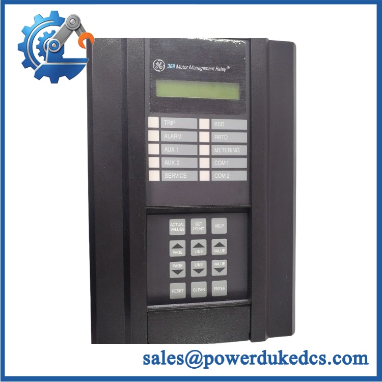
GE 369-A200
Application Scenarios & Pain Points
During a motor trip investigation, an engineer may find that the relay remains powered but measured current, voltage, or status information is inconsistent with the external system. Because the 369’s measurement and I/O functions depend on internal electronics, board-level inspection becomes relevant after CT/VT wiring and external circuits have been ruled out.
In process plants, a Multilin 369 can supervise motors where loss of reliable thermal or electrical measurements creates a protection concern. The relay supports monitoring of motor operating parameters and can learn characteristics such as inrush current, cooling behavior, and acceleration time.
For utility or power-generation auxiliaries, preserving an exact internal board revision can reduce configuration uncertainty during legacy replacement work. Commercial records link 369- to 1253-0003-C4, so the replacement board should be compared against the installed assembly before release.
At installations with ambient temperatures approaching 60°C, cabinet temperature deserves direct measurement because the documented base 369 operating range reaches +60°C. Units fitted with certain communications options can have a narrower operating range, so the relay’s actual configuration should be checked.
🚨 Common Error Codes & Diagnostic Symptoms
The 369- itself is an internal electronic board, so there is no separate board-level universal error-code list. Fault diagnosis is normally performed through the complete 369 relay’s display, communications diagnostics, actual-value screens, and protection-status information.
Symptom/Code: Incorrect or unstable measured current/voltage values → Diagnosis: Possible CT/VT wiring, polarity, external signal, relay configuration, or internal analog-interface failure. GE specifically warns that CT and VT polarity must match the relay connections and that the 369’s phase-current rating must match the connected CT secondary. → Action: Verify the external measurement circuit and configuration first; replace the internal board only after the signal path has been proven healthy.
Symptom/Code: Analog measurement remains abnormal after external wiring is verified → Diagnosis: Internal analog acquisition circuitry may be defective or out of calibration. → Action: Compare relay actual values against a calibrated external instrument; isolate the board as the suspect assembly after external causes are excluded.
Symptom/Code: Multiple I/O functions become intermittent simultaneously → Diagnosis: A common internal board supply, connector, or interface fault can affect several channels at once. → Action: Inspect internal connectors and supply rails, then replace the 369- assembly when the fault follows the board.
🚨 Cross-Reference & Lifecycle Migration
Cross-Reference
The strongest available identification relationship is:
GE 369- → 1253-0003 / 1753-0003 / 840501
A separate commercial listing identifies 1253-0003-C4 as the Multilin 369- Analog & I/O Board.
These numbers should be used as search and identification references, not as unconditional interchangeability statements. Before ordering, compare:
- Existing board part number and suffix
- PCB revision
- Connector arrangement
- Board markings
- Host 369 relay revision
- Installed firmware revision
- Relay ordering code
Firmware Requirement
The complete 369 relay has field firmware and a documented firmware history. However, no independently controlled firmware package has been verified for the 369- PCB itself. Firmware compatibility therefore needs to be considered at the relay assembly level, not simply from the analog/I/O board number.
When replacing an internal board, retain the existing relay configuration and verify communications and protection settings after commissioning.
Lifecycle Status
Status: Legacy / Obsolete Replacement Asset
The 369 platform is an established legacy GE Multilin product family, with instruction manuals documenting revisions through at least the 3.x generation.
For buffer-stock planning, retain the exact board revision and associated 369 relay configuration. A generic “369 I/O board” inventory description is insufficient for controlled maintenance.
Field Engineer’s Tech Notes
Warning 1 — Check the CT secondary before touching the board.
GE specifically warns that the relay’s nominal phase-current input must match the CT secondary rating. Never disconnect a current-transformer secondary from an energized circuit without following the approved CT shorting procedure; an open CT secondary can create dangerous voltage.
Warning 2 — Do not blame the analog board before verifying polarity.
Incorrect CT or VT polarity can produce abnormal power measurements and residual-ground or phase-related behavior that looks like an internal relay fault. Verify polarity and wiring first (this is one of the quickest ways to avoid an unnecessary board exchange).
Strict QA & Testing SOP
Step 1 — Incoming identity check
Verify and record any secondary markings such as 1253-0003, 1753-0003, 840501, or 1253-0003-C4.
Step 2 — PCB visual inspection
Inspect the board for cracked components, discoloration, burned areas, corrosion, damaged connectors, lifted components, and evidence of previous unauthorized repair.
Step 3 — Connector inspection
Check the board-to-relay mating connectors carefully. Look for bent contacts, oxidation, contamination, damaged housings, or excessive insertion wear.
Step 4 — Electrical pre-check
Verify resistance between applicable supply and ground points before energizing. Do not apply an arbitrary voltage directly to an exposed board unless the approved test procedure specifies the injection point and voltage.
Step 5 — Relay-level test installation
Install the board only in a compatible GE Multilin 369 test chassis or complete relay assembly. Confirm that the relay powers correctly and that no unexpected hardware alarm appears.
Step 6 — Measurement verification
Inject controlled current/voltage signals through an approved test setup and compare the displayed actual values with calibrated test-instrument readings.
Step 7 — I/O verification
Check the applicable digital and analog functions supported by the particular 369 configuration. Confirm stable operation across repeated input-state changes.
Step 8 — Communications check
Verify the complete relay’s front RS232 and/or rear RS485 communications where applicable. Confirm expected Modbus data and diagnostic access.
Step 9 — Protection-function validation
Run only the protection tests authorized by the service procedure. CT/VT injection, thermal simulation, trip-output testing, and event recording should be performed with an approved relay test set.
Step 10 — Final packaging
Record the board identity, revision, test results, photographs, and serial/lot information. Package the PCB in ESD shielding material with mechanical protection around connectors.
Test videos are available for applicable tested units, subject to the available GE 369 test configuration.
Buyer’s FAQ
Can the 369- be hot-swapped?
Do not treat it as a hot-swappable plug-in I/O module. The 369- is an internal relay board, and safe replacement requires the complete relay’s approved maintenance procedure. Control power and potentially hazardous measurement circuits must be considered before opening the relay.
How do I verify a New Original 369-?
Request photographs of the actual PCB, including the GE marking, 1253-0003 or related assembly number, revision suffix, connector area, and component condition. A generic photograph of a Multilin 369 relay does not prove that the supplied board is the requested revision.
Is 1253-0003-C4 the same as 369-?
Current commercial records associate 1253-0003-C4 with the 369- Analog & I/O Board, while other records list 1253-0003, 1753-0003, and 840501 as related identifiers. Confirm the complete marking and host-relay compatibility before approving a substitution.
What warranty should I expect?
Warranty depends on the supplier’s written terms and whether the board is sold as New Original, New Surplus, refurbished, or used. For a legacy internal board, request the warranty period, functional test evidence, return conditions, and identification photographs before purchase.
A one-year warranty should not be presented as a GE factory warranty unless the manufacturer has expressly provided that coverage.











 Start Chat


