

Description
- Brand: GE Multilin
- Full Model Number: 369-HI-R-0-0-0-0-E
- System/Series Family: GE Multilin 369 Motor Management Relay
- Core Function: Three-phase motor protection, monitoring, metering, and management
- Top 3 Hardcore Specs: 50–300 VDC / 60–265 VAC control power; 12 built-in RTD inputs; Enhanced diagnostics and faceplate
- Stock Status: New Surplus — exact hardware revision and condition to be confirmed before shipment
GE’s official 369 instruction manual confirms that 369-HI-R-0-0-0-0-E specifies HI control power, the R option with 12 RTD inputs, no metering, fiber-optic, or additional protocol options in the corresponding positions, and the E enhanced diagnostics option.
Module 3: Technical Product Introduction
When a motor protection relay fails, the problem extends beyond a protective trip: the replacement must reproduce the installed CT, RTD, control-power, communication, and protection configuration. The GE Multilin 369-HI-R-0-0-0-0-E is a motor management relay configured with HI control power, 12 built-in RTD inputs, and Enhanced diagnostics. GE’s manual identifies the HI supply range as 50–300 VDC / 60–265 VAC and specifies that the 369 is available in a non-drawout version.
The R option provides 12 RTD inputs, while the E option adds the enhanced faceplate, motor status indicators, Motor Health Report, enhanced learned data, motor start data logging, enhanced event recording, and security audit trail events. The model’s four intermediate option positions are not interchangeable placeholders; each character defines a particular hardware or communication feature. That makes the complete ordering code essential when replacing an installed relay. A technically similar 369 with a different option string should not be treated as an automatic substitute.
Module 4: Application Scenarios & Field Realities
- For large three-phase motor protection panels, the 369 monitors motor operating conditions while providing protective functions through its configured CT and RTD inputs. The 12-RTD option is particularly relevant where bearing, stator, or ambient temperature monitoring is part of the protection scheme.
- In pump and compressor applications, a failed relay can prevent motor restart even when the motor and starter remain electrically healthy. Keeping the exact 369 option code available avoids rebuilding the protection configuration around a different relay.
- During motor commissioning, verify the CT secondary rating before applying protection settings. The 369 supports 1 A and 5 A phase-current inputs, so the relay configuration must correspond to the installed CT secondary.
- For maintenance of an existing 369 installation, preserve the original setpoints before replacing the relay. Record protection settings, RTD assignments, communications parameters, and event-related configuration first. The replacement should then be checked against those records rather than configured from memory.
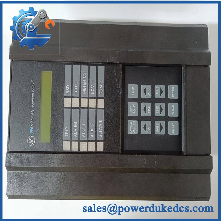
GE 369-HI-R-0-0-0-0-E
Module 5: Migration, Compatibility & Installation Traps
Replacement Matrix
| Replacement Type | 369-HI-R-0-0-0-0-E Assessment | Engineering Requirement |
|---|---|---|
| Drop-in Replacement | Yes, for an exact option-code match | Match complete ordering code, control power, RTD option, firmware/hardware revision, and wiring |
| Software Compatible | Configuration-dependent | Transfer and verify protection setpoints and communication parameters |
| Hardware Modification Required | Potentially required for a different option code | Different RTD, communications, metering, or control-power options can require different hardware |
Field Trap 1 — The option code is the specification:
GE states that the 369 ordering code contains 10 digits/positions and that the control-power selection must be specified. An unused feature is represented by 0. The exact string 369-HI-R-0-0-0-0-E therefore matters.
Field Trap 2 — Do not assume field upgrades are purely software:
GE’s manual states that field upgrades are possible only when the required hardware was installed at the factory, with an option-enabling passcode used for applicable upgrades. GE also states that unauthorized hardware modifications can void the product warranty and are not supported.
Installation note: Isolate the relay and associated control circuits according to the plant procedure. Record terminal assignments before removal. Pay particular attention to CT circuits; never open-circuit an energized CT secondary. Verify the 12 RTD wiring and polarity/connection arrangement before restoring the relay to service.
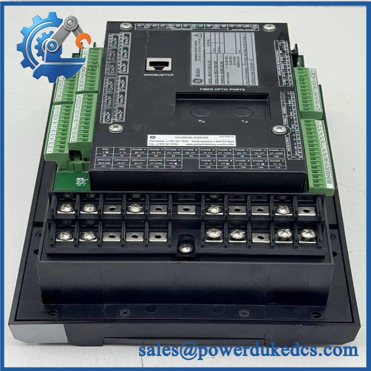
GE 369-HI-R-0-0-0-0-E
Module 6: Quality Assurance SOP
- OEM identification inspection — Verify the complete 369-HI-R-0-0-0-0-E ordering code, GE Multilin markings, serial information, rating labels, and hardware revision.
- Physical inspection — Examine the enclosure, terminal blocks, front panel, display, connectors, mounting points, and internal accessible areas for cracks, contamination, corrosion, impact marks, or unauthorized modifications.
- OEM anti-counterfeit visual inspection — Compare GE labeling, enclosure construction, PCB markings, connector arrangement, and model identification against known 369 hardware.
- Power-on self-test (POST) — Energize the relay with the correct HI control supply under controlled test conditions and verify startup behavior, display operation, status indications, and diagnostic messages.
- RTD input verification — Test the available 12 RTD channels using an appropriate simulator or resistance source. Confirm that representative temperature values are correctly recognized by the relay.
- Communication handshake verification — Where the installed configuration supports a communication interface, establish the applicable test connection and verify stable communication with the relay. Do not assume a communication option exists merely because another 369 variant has it.
- Protection-function verification — Apply controlled simulated current and temperature conditions where the test facility permits. Verify applicable alarm, trip, measurement, and status responses against the approved test procedure.
- Configuration and setpoint check — Confirm that the relay’s programmed protection parameters correspond to the customer’s approved settings. Record any deviation before shipment.
- Final traceability record — Photograph the complete model label and front panel, record serial/revision information, document test results, and complete an ESD-safe packaging inspection.
For this particular relay, 369-HI-R-0-0-0-0-E should be treated as a complete configuration code rather than simply “GE 369.” The HI control-power range, 12-RTD option, and Enhanced option are all encoded in that ordering string, and GE’s manual specifically defines those positions.











 Start Chat


