

Description
- Brand: GE Multilin
- Full Model Number: 369-HI-R-0-0-0-E
- Product Type: Motor Management / Protection Relay
- System/Series Family: GE Multilin 369 Motor Management Relay
- Core Function: Motor protection, monitoring, metering, and control for low- and medium-voltage motors
- Top 3 Hardcore Specs: 369 relay platform | 50 A CT input class | 120 VAC control power
- Application: Motor protection and management
- Communications: RS485 / Modbus RTU capability on applicable 369 configurations
- Stock Status: New surplus / condition to be confirmed per available unit
The GE Multilin 369 is a motor management relay designed for protection, monitoring, metering, and control of motors. The exact suffix 369-HI-R-0-0-0-E defines a particular hardware/configuration combination, so the complete ordering code should be retained when replacing an installed relay. The 369 platform supports functions such as overload, phase loss, phase reversal, current imbalance, undercurrent, ground fault, and other motor protection functions depending on configuration.
Module 3: Technical Product Introduction
A motor protection relay is the device that decides whether abnormal electrical conditions should trip the motor before the fault develops into winding damage or prolonged mechanical stress. GE 369-HI-R-0-0-0-E belongs to the Multilin 369 motor management relay family, providing protection and monitoring functions for industrial motors. In a replacement situation, the relay configuration matters because CT input ranges, control power, communications, and available protection functions can vary between ordering-code variants.
The 369 platform combines motor protection with electrical measurement and control functions, allowing operators and maintenance personnel to evaluate motor current and operating conditions from the relay rather than relying solely on upstream breakers. For a replacement, confirm the existing CT secondary arrangement, control voltage, trip/auxiliary contact wiring, and communication configuration. —Never assume that a relay with the same 369 family name has the same terminal assignment or hardware options as the installed suffix.
Module 4: Application Scenarios & Field Realities
- On large induction motors driving pumps, fans, and compressors, the relay can monitor current-based operating conditions and initiate protection when the motor moves outside its configured operating envelope. CT ratio and full-load current settings must be entered correctly after replacement.
- For critical process motors, protection coordination becomes more important than simply restoring a trip signal. The 369 should be checked against the existing upstream breaker, contactor, overload, and ground-fault protection settings so that a replacement does not introduce an unwanted coordination problem.
- During motor-start troubleshooting, examine acceleration time and starting current before changing overload settings. A relay that trips only during starting may be correctly detecting an improperly configured acceleration profile rather than suffering from an internal fault.
- In plants using supervisory monitoring, the relay’s communications configuration should be documented before removal. RS485/Modbus RTU installations depend on correct addressing, baud rate, parity, termination, and register mapping; a replacement relay can operate locally while still being invisible to the control system if those settings are wrong.
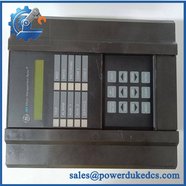
GE 369-HI-R-0-0-0-E
Module 5: Migration, Compatibility & Installation Traps
Replacement Matrix
| Replacement Type | 369-HI-R-0-0-0-E Assessment |
|---|---|
| Drop-in Replacement | Yes, when replacing the same 369-HI-R-0-0-0-E configuration with matching hardware and terminal arrangement |
| Software Compatible | Configuration-dependent; protection settings and communication parameters must be restored and verified |
| Hardware Modification Required | Not expected for an exact replacement; required if CT, control-power, I/O, or communication options differ |
Field Traps — Watch Out
1. CT wiring must be documented before removal.
Record each CT input and polarity connection before disconnecting the old relay. Incorrect CT polarity or phase assignment can produce incorrect current measurements and cause phase, power, or protection calculations to behave unexpectedly.
2. Protection settings are not generic.
Do not commission a replacement using factory defaults. Restore the motor’s documented full-load current, CT ratio, overload class, acceleration time, ground-fault settings, trip delays, and other site-approved parameters.
3. Verify the control-power variant.
The exact 369 ordering code determines hardware configuration. Confirm the installed control supply and relay nameplate before applying power.
4. Check communications after local testing.
For installations using RS485/Modbus RTU, verify the relay address, baud rate, parity, stop bits, network polarity, and termination. Local relay operation does not prove that the supervisory system will communicate correctly.
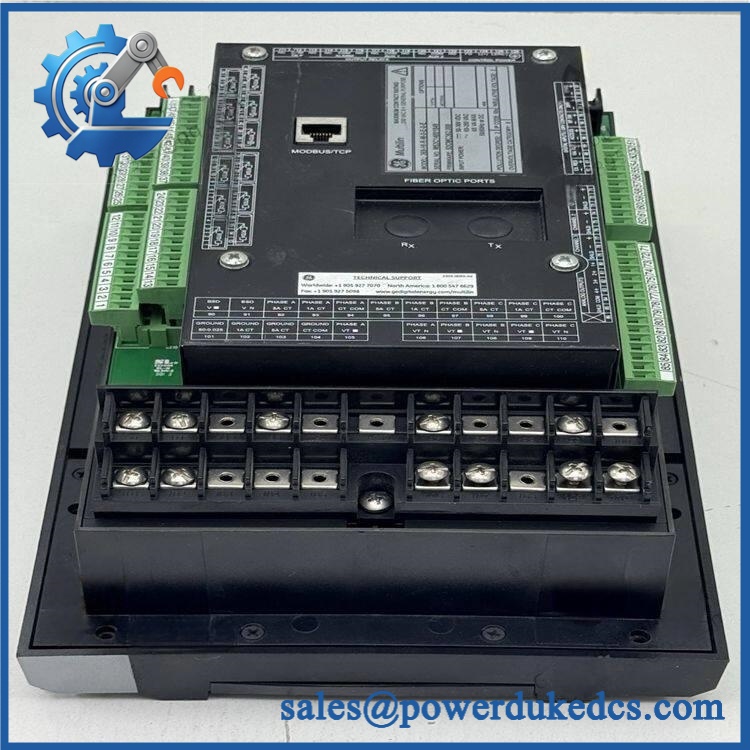
GE 369-HI-R-0-0-0-E
Module 6: Quality Assurance SOP
Before shipment, each available GE 369-HI-R-0-0-0-E should pass a documented relay-testing sequence:
- OEM identification inspection — Verify GE Multilin markings, complete 369-HI-R-0-0-0-E ordering code, serial information, hardware revision, and front-panel labels.
- OEM anti-counterfeit visual inspection — Examine the enclosure, display/keypad, terminal blocks, PCB workmanship, labels, connectors, and fasteners for evidence of unauthorized modification.
- Physical inspection — Check terminals, mounting points, display, keypad, communication ports, and enclosure for corrosion, cracking, contamination, or mechanical damage.
- Part-number verification — Match the physical relay against the customer’s exact 369-HI-R-0-0-0-E requirement before testing.
- Controlled power-on test — Apply the correct control power under laboratory conditions and verify normal startup and diagnostic status.
- Display/keypad verification — Confirm the front-panel display and operator controls respond correctly across representative menu functions.
- Metering verification — Apply controlled simulated current/voltage inputs within the relay’s specified test limits and confirm expected measurement behavior.
- Protection-function simulation — Where the appropriate relay test set is available, simulate representative overload, phase-loss, imbalance, undercurrent, and ground-fault conditions and verify pickup/trip behavior against the configured settings.
- Trip-output verification — Confirm that the applicable relay output contacts change state correctly during controlled protection tests.
- Communication handshake verification — Connect the relay to a compatible RS485/Modbus RTU test environment where applicable and verify addressing, communication, and data exchange.
- Event/diagnostic verification — Check relay diagnostics and event records for unexpected hardware or self-test faults.
- Final inspection and packaging — Record model number, revision, test results, inspection date, and packaging condition before dispatch.
QA note: A protection relay should not be certified merely by powering it on and observing the display. For the GE Multilin 369 platform, simulated protection inputs, trip-output testing, metering verification, and communication testing provide substantially stronger evidence of operational condition.











 Start Chat


