

Description
- Model: 369-HI-R-M-0-0
- Brand: General Electric (GE) Multilin
- Series: Multilin 369 Motor Management Relay
- Part Type: Digital Motor Management / Protection Relay
- Core Function: Protects, monitors, and manages medium-size AC motors using electrical measurements, thermal modeling, RTD temperature inputs, and programmable protection functions.
- Key Specs: HI high-range control power, 12 built-in RTD inputs, M metering package, no optional fiber-optic port, and no optional Profibus/DeviceNet/Modbus-TCP interface. The older GE ordering documentation explicitly uses 369-HI-R-M-0-0 as a valid example configuration.
Product Introduction
The GE Multilin 369-HI-R-M-0-0 is a non-drawout motor management relay for medium-size three-phase motors. In the GE ordering structure, HI specifies the high-range control-power version, R adds 12 built-in RTD inputs, and M adds the metering package; the two trailing zero positions indicate no optional fiber-optic interface and no optional protocol interface.
For a legacy motor-protection cabinet, that exact option string matters. The 369 can monitor current, voltage, power, frequency, energy, temperature, and motor thermal state while executing protection functions such as overload, current unbalance, ground fault, undervoltage, overvoltage, and mechanical-jam protection. This makes the relay a configuration-controlled asset rather than a generic “369 replacement” (the installed option code should be copied from the nameplate before procurement).
Core Technical Specifications
| Parameter | Value |
|---|---|
| Manufacturer | General Electric (GE) / GE Multilin |
| Model | 369-HI-R-M-0-0 |
| Product Family | Multilin 369 |
| Product Type | Digital Motor Management Relay |
| Construction | Non-drawout relay |
| Control Power Option | HI |
| HI Control Power | 50–300 VDC / 40–265 VAC, 50/60 Hz in the documented ordering generation |
| RTD Option | R |
| Built-In RTD Inputs | 12 |
| Metering Option | M |
| Metering | Voltage, watts, VAR, VA, power factor, frequency, and energy functions |
| Fiber Interface | 0 — no optional fiber-optic port |
| Protocol Interface | 0 — no optional Profibus, Profibus-DPV1, DeviceNet, or Modbus/TCP option |
| Base Analog Outputs | 1 |
| Additional Analog Outputs with M Option | 3 |
| Output Relay Rating | Up to 250 VAC, 8 A resistive; documented motor-load ratings also apply |
| Phase Current Measurement | True RMS conversion; approximately 1.04 ms/sample |
| Voltage Measurement | 0–240 V wye or delta VT connections for the metering configuration |
| Ground Current Input | 5 A, 1 A, and 50:0.25 tap options |
| Communication Ports | Standard RS232 and RS485 interfaces |
| Typical Protocol | Modbus RTU through the standard serial architecture |
| Operating Temperature | -40°C to +60°C for the base configuration |
| Operating Temperature with Optional Protocol Modules | +5°C to +60°C for the documented Profibus/Modbus-TCP/DeviceNet configurations |
| Storage Temperature | -40°C to +80°C base configuration |
| Humidity | Up to 95%, non-condensing |
| Enclosure Protection | IP50 in the documented relay specification |
| Overvoltage Category | II |
| Pollution Degree | 2 |
| Approximate Dimensions | 29.6 × 10.7 × 20.5 cm (H × W × D) |
| Approximate Relay Weight | 4.5 kg |
| Factory Firmware | Revision varies by production date; record the actual displayed firmware revision |
GE’s manual confirms the ordering structure, HI/R/M options, serial communications, measurement architecture, environmental specification, and relay-label fields. The same manual states that the factory-installed firmware shown on the label may no longer be the current firmware, because field upgrades are possible.
The approximate 4.5 kg weight and 29.6 × 10.7 × 20.5 cm envelope are reported by current commercial technical records. These are suitable for preliminary logistics calculations; use the actual packed dimensions and weight for a commercial invoice.
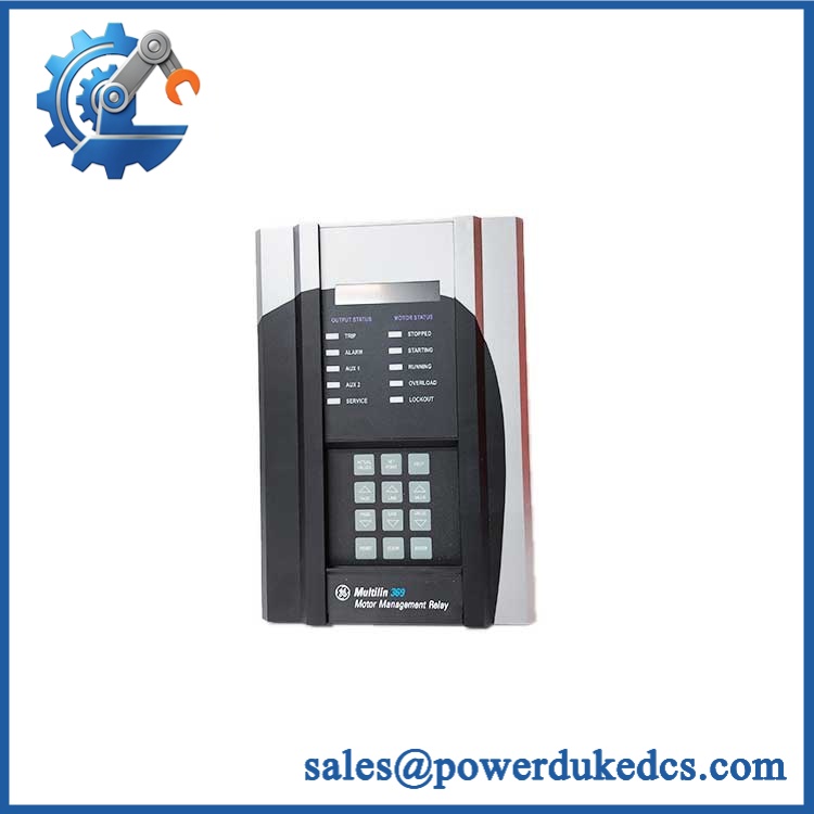
GE 369-HI-R-M-0-0
Application Scenarios & Pain Points
Micro-case — large motor trip with healthy upstream switching gear. A motor starter can energize correctly while the 369 still detects an electrical or thermal condition that blocks continued operation. The relay combines protection, metering, learned motor data, and RTD inputs in one device, which is why a single incorrect setting can affect several observed functions.
In process plants, the 12-RTD configuration is useful where winding and bearing temperatures must be monitored together with electrical loading. RTD-biased thermal protection and bearing-temperature functions are both included among typical 369 applications.
For pumps and rotating equipment, the metering package supplies values such as watts, VAR, VA, power factor, frequency, and energy, allowing operators to compare motor loading against process conditions. A power-factor or energy-reading discrepancy should therefore be checked against CT/VT wiring before condemning the relay.
At cabinets exposed to 50°C+ ambient conditions, the base relay remains within its documented +60°C operating limit, but the actual enclosure temperature still controls the margin available to the electronics. The optional communication-module temperature restriction is different, which is another reason the exact order code must be retained.
🚨 Common Error Codes & Diagnostic Symptoms
The 369 is primarily diagnosed through its LCD, actual-value menus, event records, LED indications, and protection-status messages rather than a single universal numerical error-code table. GE also provides model and firmware information through the A6 Relay Information menu.
Symptom/Code: Phase current or voltage actual values do not agree with calibrated external instruments → Diagnosis: Possible CT/VT polarity error, incorrect scaling, wiring fault, or internal measurement-channel problem. GE specifically requires the current-input and CT arrangement to match the relay configuration. → Action: Verify CT/VT wiring and settings first; replace the relay only after the external measurement path is proven correct.
Symptom/Code: Multiple RTD channels show abnormal temperature or fail together → Diagnosis: Possible RTD wiring issue, common supply/reference fault, or internal RTD interface failure. → Action: Check each sensor and field circuit, then compare the affected channels; replace the relay if the fault remains with the relay hardware.
Symptom/Code: Relay remains powered but protection, metering, or event functions behave abnormally → Diagnosis: Possible internal processing, memory, or configuration corruption. The 369 stores firmware and configuration information internally, and the actual firmware revision can be checked from the relay information menu. → Action: Capture settings and firmware data, perform the approved diagnostic procedure, and replace the relay if the hardware fault is confirmed.
🚨 Cross-Reference & Lifecycle Migration
Option-Code Cross-Reference
The correct interpretation of the supplied model is:
369-HI-R-M-0-0
- 369 — Multilin 369 base relay
- HI — high-range control power
- R — 12 built-in RTD inputs
- M — metering package
- 0 — no optional fiber-optic port
- 0 — no optional protocol interface
GE’s own documentation uses 369-HI-R-M-0-0 as the example of a relay with HI control power, 12 RTDs, and the metering option.
Some later documents show an expanded ordering format ending in an additional harsh-environment and enhanced-diagnostics field. Therefore, do not assume that a similarly named 369-HI-R-M-0-0-0 or 369-HI-R-M-0-0-0-E has the same factory options as the buyer-supplied six-segment code.
Firmware
Firmware flashing may be applicable to the complete 369 relay, not to an abstract order-code option. GE’s manual provides a dedicated firmware-information screen and notes that the factory firmware shown on the relay label can be different from the currently installed revision because field upgrades are supported.
Before migration, record:
- Firmware revision
- Boot revision
- Installed option code
- Serial number
- Last calibration date
- Protection and metering settings
Lifecycle Status
Status: Legacy / Obsolete Platform
The Multilin 369 is a mature legacy relay family. Current market availability is primarily through existing inventory, surplus stock, or repair channels rather than a typical current-production procurement cycle.
For buffer stock, retain the complete option code, not merely “GE 369.” A spare with the wrong CT range, RTD configuration, communications option, or control-power class can create a commissioning failure even though its front panel appears identical.
Field Engineer’s Tech Notes
Warning 1 — Never open a live CT secondary.
Before disconnecting the relay, isolate and properly short the CT secondary according to the site’s approved procedure. An energized CT with an open secondary can develop hazardous voltage; this is not a routine continuity-check situation.
Warning 2 — Copy the nameplate before changing the relay.
The GE label records the ordered model, serial number, factory firmware, installed options, input-power range, certifications, pollution degree, IP code, and overvoltage category. Photograph that label first. A replacement selected only by “369” can silently change the RTD, metering, communications, or control-power configuration.
Strict QA & Testing SOP
Step 1 — Identity inspection
Verify the full 369-HI-R-M-0-0 code where present, then photograph the serial number, firmware label, modification field, and certification markings.
Step 2 — Mechanical inspection
Check the front bezel, LCD, keypad, rear terminals, mounting points, housing, and connector condition for cracking, corrosion, contamination, or mechanical distortion.
Step 3 — Power-input verification
Confirm that the test source matches the HI control-power rating. The documented HI range is 50–300 VDC or 40–265 VAC for the applicable manual generation.
Step 4 — Controlled energization
Power the relay on an approved test fixture and verify normal startup, LCD function, keypad response, status LEDs, and absence of unexpected hardware diagnostics.
Step 5 — Firmware and identity capture
Enter the relay information menu and record firmware revision, boot revision, serial number, manufacture date, and last calibration information. GE provides these values through the actual-values menu.
Step 6 — Current/voltage injection
Use a calibrated relay test system to inject representative current and voltage signals. Compare measured values with the 369 actual-value screens and verify correct scaling and phase relationships.
Step 7 — RTD testing
Simulate or connect approved RTD inputs and verify all applicable channels. Confirm that temperature values change correctly and that no unexpected RTD alarm appears.
Step 8 — Metering verification
Check voltage, current, watts, VAR, VA, power factor, frequency, and energy functions associated with the M option.
Step 9 — Protection-function test
Run only approved secondary-injection tests for overload, phase loss/unbalance, ground fault, under/overvoltage, mechanical jam, and other configured functions. Record trip thresholds and timing against the approved settings.
Step 10 — Communications and record package
Because the supplied model specifies no optional protocol interface, verify the standard serial interfaces as applicable rather than assuming Ethernet, Profibus, or DeviceNet capability. Store the settings file, test results, photographs, and serial number with the asset.
Step 11 — Final packaging
Protect the keypad, LCD, rear terminals, and housing with impact-resistant material. Use ESD precautions and keep the relay immobilized inside the export carton.
Test videos are available for applicable tested units.
Buyer’s FAQ
Can I hot-swap the 369-HI-R-M-0-0?
Do not treat this relay as a hot-swappable I/O card. The 369 is a complete motor-protection device with CT, VT, RTD, control-power, and trip circuitry. Use the approved shutdown and isolation procedure, including CT-secondary precautions, before removal.
How do I verify a New Original GE 369-HI-R-M-0-0?
Request photographs of the actual nameplate and front/rear assemblies. Verify the complete option code, serial number, factory firmware, input-power rating, certification markings, and physical condition. GE’s manual specifically identifies these fields on the relay label.
Does this model include metering and 12 RTD inputs?
Yes. In the GE ordering structure, R specifies the optional 12 built-in RTD inputs, while M specifies the metering package. The exact buyer-supplied code therefore represents a 369 with both features.
What warranty should I expect?
Warranty depends on the seller’s written terms and the condition category of the unit. For obsolete or legacy 369 hardware, request the warranty period, test coverage, return conditions, actual serial number, and firmware information before issuing the purchase order. A third-party seller’s warranty should not be represented as a GE factory warranty.











 Start Chat


