

Description
-
Model: GE 8810-HI-TX-01
- Brand: GE / GE Intelligent Platforms
- Series: PAC8000 Modular I/O / SafetyNet
- Part Type: 8-channel safety analog input module
- Core Function: Acquires single-ended 4–20 mA transmitter signals and provides HART communication through the PAC8000 safety I/O architecture.
- Key Specs: 8 channels; 4–20 mA nominal input; 0.25–24 mA full input range; 16-bit resolution; HART pass-through, acquisition and status reporting; 25 ms signal processing; 24 VDC bussed field power; 70 mA system current and 350 mA field current.
Product Introduction
The GE 8810-HI-TX-01 occupies an analog-input position in the PAC8000 safety I/O architecture, where it acquires process transmitter signals for control and safety applications. Eight single-ended channels accept 4–20 mA signals, with the published full input range extending from 0.25 to 24 mA. HART information can be passed through, acquired, and reported as status data, allowing maintenance personnel to obtain transmitter information without installing a separate HART interface.
For a safety-system replacement, exact module identification is critical. The available technical records identify the unit as an 8810-HI-TX SafetyNet analog-input module, while supplier records consistently add the -01 suffix. Public records disagree on the claimed SIL level—some state SIL 2, while others incorrectly state SIL 3—so the safety integrity claim should be tied to the applicable certificate and exact hardware configuration rather than a reseller description. (This distinction is important when the module enters a functional-safety asset register.)
Core Technical Specifications
| Parameter | Value |
|---|---|
| Manufacturer | GE / GE Intelligent Platforms |
| Catalog Number | 8810-HI-TX-01 |
| Product Family | PAC8000 / SafetyNet |
| Hardware Type | Safety analog input module |
| Number of Channels | 8 |
| Input Type | Single-ended analog current |
| Nominal Input Range | 4–20 mA |
| Full Input Range | 0.25–24 mA |
| Resolution | 16 bit |
| Data Format | 16-bit unsigned |
| HART | Pass-through, acquisition, and status reporting |
| HART Data Format | IEEE 754 floating point |
| Transmitter Wiring | 2-wire, 3-wire, or 4-wire |
| Input Circuit Type | Non-incendive field circuits |
| Signal Processing Time | 25 ms |
| Accuracy at 25°C | ±0.1% of span |
| Temperature Coefficient | 38 ppm/°C |
| Repeatability | 0.05% of span |
| Channel-to-Railbus Isolation | 250 VAC RMS |
| Channel-to-Channel Isolation | None |
| Required Field Power | 24 VDC bussed field power |
| System Current | 70 mA |
| Field Current | 350 mA |
| Mounting | PAC8000 carrier |
| Module Width | 42 mm |
| Module Weight | 200 g |
| Operating Temperature | −40 to +70°C |
| Recommended Field-Terminal Family | Compatible PAC8000 field terminals; verify exact terminal against installation documentation |
| Safety Application | SafetyNet; published records identify SIL 2, while other secondary sources claim SIL 3 |
| Lifecycle | Legacy hardware |
The 8-channel count, signal range, 16-bit conversion, HART functionality, isolation, current consumption, physical width, and weight are consistently reported for the 8810-HI-TX family.;
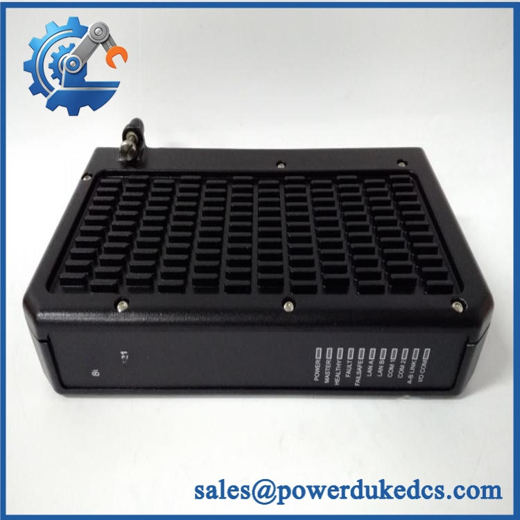
GE 8810-HI-TX-01
Application Scenarios & Pain Points
A process transmitter stops updating correctly while the field instrument itself continues to generate a valid current signal. The 8810-HI-TX-01 provides eight separate analog acquisition channels, allowing maintenance personnel to isolate transmitter, wiring, field-terminal, and I/O-module faults.
In oil and gas process applications, the 4–20 mA channels can acquire pressure, flow, level, temperature, and other transmitter outputs, while HART data provides an additional diagnostic and configuration path. The published architecture supports 2-, 3-, and 4-wire transmitters.
For process safety systems, the distinction between a standard analog input and a safety-rated analog input matters at the asset-management level. A safety I/O module is evaluated as part of a defined system architecture; certification cannot be inferred solely from the module’s electrical specifications.
In hazardous-area installations, the documented non-incendive field-circuit designation can be relevant to the installation concept. The field terminal, wiring method, barrier/interface arrangement, enclosure, and certification conditions must all match the approved system design.
At 50°C+ ambient temperatures, the specified −40 to +70°C operating envelope provides useful margin, but accuracy changes with temperature. The documented accuracy is ±0.1% of span at 25°C, with a temperature coefficient of 38 ppm/°C.
🚨 Common Error Codes & Diagnostic Symptoms
The public documentation reviewed does not establish a universal numerical fault-code list specifically for 8810-HI-TX-01. Troubleshooting should therefore begin with channel status, transmitter current, field power, HART diagnostics, and node status.
Symptom/Code: Analog channel reports an open or invalid transmitter signal → Diagnosis: Possible broken loop conductor, missing 24 VDC field power, loose field-terminal connection, transmitter failure, or input-channel fault → Action: Measure the field loop independently, verify the field terminal, then replace the module if a known-good current source produces the same fault.
Symptom/Code: Correct 4–20 mA signal present, but process value is incorrect → Diagnosis: Possible scaling/configuration error, transmitter configuration problem, wiring error, or analog-input circuitry fault → Action: Inject a calibrated current at several test points and compare the value with the expected engineering-unit conversion.
Symptom/Code: HART communication unavailable while analog current remains valid → Diagnosis: HART device configuration, loop impedance, wiring, field power, or module HART circuitry may be involved; loss of HART communication does not automatically indicate loss of the analog channel → Action: Check the HART loop conditions and transmitter first, then test the module with a known-good HART source.
🚨 Cross-Reference & Lifecycle Migration
Exact Part Identity
The correct functional identification is:
GE 8810-HI-TX-01 — 8-channel Safety Analog Input with HART
The 8810-HI-TX designation appears consistently in technical listings, while 8810-HI-TX-01 is the full commercial part number used by current industrial suppliers.;
Do not substitute an ordinary analog-input module merely because it has eight channels and a 4–20 mA range. Safety functions, certification, diagnostics, field-terminal requirements, and system configuration can differ.
Field-Terminal Compatibility
The module must be installed with an approved field terminal. Published safety documentation identifies compatible terminal families including 8601-FT-NI, 8603-FT-FU, 8615-FT-4W, 8616-FT-FU, 8618-FT-MT, and 8619-FT-MT for applicable configurations. Exact terminal selection depends on the field circuit and hazardous-area arrangement.
Firmware Requirement
The 8810-HI-TX-01 is an I/O module rather than a general-purpose PLC CPU. No normal user firmware-flashing procedure has been established for the module itself.
Configuration is performed through the /SafetyNet system, including channel assignments, signal handling, transmitter configuration, HART data, alarms, and safety-system parameters.
Do not update or replace a safety I/O module based on firmware assumptions alone. Confirm the exact SafetyNet controller, I/O configuration, module revision, and approved system configuration.
Safety Certification Warning
Public secondary sources conflict on the safety integrity level. One current technical record identifies the module as SIL 2, while other reseller pages claim SIL 3 without presenting a corresponding certificate.;
For a functional-safety audit, use the certificate and safety manual applicable to the exact module and system configuration. Do not populate a safety database with SIL 3 solely from a reseller listing.
Lifecycle Status
Lifecycle: Legacy hardware.
The 8810-HI-TX-01 remains represented in documentation and industrial spare-parts inventories, but the platform is an established legacy architecture. For safety-related installations, retain exact module identification, field-terminal information, certification evidence, and replacement test records.
Field Engineer’s Tech Notes
First warning: verify the 24 VDC field-power arrangement before diagnosing a dead transmitter. The module relies on 24 VDC bussed field power, and a common field-power problem can affect several channels simultaneously.
Second warning: do not confuse HART failure with analog-input failure. A transmitter can continue producing a correct 4–20 mA signal while its digital HART communication is unavailable. Test the analog loop independently before replacing the 8810-HI-TX-01.
For safety applications, do not bypass the approved field terminal or change wiring topology during troubleshooting. A temporary bench connection can invalidate the assumptions behind the certified installation.
Strict QA & Testing SOP
1. Inbound identity verification
Confirm 8810-HI-TX-01 on the physical label. Record serial number, hardware revision, date code, safety markings, and packaging condition.
2. Physical inspection
Examine the 42 mm housing, carrier interface, field connector, labels, keying arrangement, and enclosure for cracks, corrosion, contamination, or mechanical damage.
3. Certification review
Record the actual certification markings and compare them with the applicable /SafetyNet safety documentation. Do not infer SIL capability from the base catalog number.
4. Field-terminal verification
Confirm the installed or supplied terminal is approved for the module and intended field circuit. Check mechanical keying before insertion.
5. Power inspection
Verify the Railbus and 24 VDC bussed field power. The documented module consumption is approximately 70 mA system current and 350 mA field current.
6. Analog signal simulation
Use a calibrated current source to exercise all eight channels at representative values across the 4–20 mA range.
7. Accuracy verification
Check representative points against the published ±0.1% of span at 25°C accuracy specification, accounting for the specified temperature coefficient.
8. Open/low/high current testing
Test current below the nominal span and above the normal operating range within safe laboratory limits. Confirm the programmed diagnostic and scaling response.
9. HART verification
Connect a known-good HART transmitter or simulator. Confirm pass-through, acquisition, and HART status reporting.
10. Isolation verification
Where the safety test environment permits, verify the documented 250 VAC RMS channel-group-to-Railbus isolation using an approved test procedure.
11. Safety-system integration test
Install the module on a verified /SafetyNet test system and confirm channel status, diagnostic handling, data transfer, and configured safety behavior.
12. Extended observation
Monitor all channels for drift, intermittent loss, HART instability, field-power abnormalities, and Railbus communication interruptions.
13. Final preservation
Place the tested module in ESD-safe packaging, protect the field connector, preserve certification labels, and attach the complete QC record.
Test videos are available when live functional verification is performed and visual evidence is required for procurement approval.
Buyer’s FAQ
Is 8810-HI-TX-01 really a safety-rated module?
It is identified in current technical records as a Safety Analog Input module. However, published secondary sources disagree about whether the applicable safety capability is SIL 2 or SIL 3. Use the exact OEM/certification documentation for the installed hardware and SafetyNet configuration rather than relying on an online product description.
Can I replace it while the node is energized?
Do not assume unrestricted hot replacement. Some documentation describes controlled replacement procedures, but safety-system maintenance must follow the specific carrier, field-power, hazardous-area, and site isolation procedures. Disconnecting the associated Bus Field Power and following the approved replacement sequence may be required for the installation.
How do I verify New Original authenticity?
Request photographs of the actual 8810-HI-TX-01, including the GE identification label, hardware revision, serial/date information, safety markings, connector arrangement, and factory packaging. The exact part identity should remain visible in the incoming inspection record.
Does it include the latest firmware, and what warranty applies?
This is an I/O module rather than a conventional PLC CPU with a user-managed firmware package. Verify the actual hardware revision and /SafetyNet compatibility instead of requesting a generic “latest firmware” statement.
For warranty control, specify New Original, New Surplus, or refurbished condition, the functional-test scope, serial-number coverage, and warranty period on the purchase documentation. For a safety-related spare, retain the test report and certification evidence together with the asset record.











 Start Chat


