

Description
- Model & Brand: GE Fanuc BK698CPA15B0, identified in current supplier records as a VME64 controller module / control processor board.
- Physical Dimensions: A reliable GE mechanical drawing for this exact catalog number was not located. One aftermarket record reports approximately 100 × 150 × 50 mm, while another gives 233 × 160 × 30 mm for a 6U VME implementation. The discrepancy is too large for certified cabinet planning.
- Estimated Shipping Weight: Current supplier records range from approximately 0.3 kg to 1.8 kg. These figures are inconsistent and should not be used for final freight documents without weighing the actual packed unit.
- What’s in the Box: Normally the BK698CPA15B0 controller module. Do not assume the VME backplane, transition module, memory accessory, cables, or software media are included.
- Mounting Concept: VME rack installation is consistently associated with the part. The exact rack/card-guide arrangement should be matched to the installed system before ordering a replacement.
- Packaging: For New Original or New Surplus stock, retain the factory identification label, ESD packaging, serial information, and carton markings together.
Product Introduction
Inside a legacy VME-based GE control system, the BK698CPA15B0 functions as a controller/processor board rather than a conventional field I/O module. Its role is tied to VMEbus communication and host-system processing, so the rack, backplane, application software, and system configuration all form part of the replacement decision.
The available market descriptions are not sufficiently consistent to justify assigning a specific processor, memory capacity, power rail, or Ethernet configuration to every BK698CPA15B0. Some listings describe it as a VME64 controller with RS-232/RS-485 communications and 24 VDC input, while another gives a 6U VME single-board-computer profile with a Pentium III processor and 5 V VME backplane power. Those differences should be resolved from the physical board and original GE documentation before engineering approval.
Core Technical Specifications
| Parameter | Value |
|---|---|
| Manufacturer | GE / GE Fanuc |
| Exact Part Number | BK698CPA15B0 |
| Product Type | VME64 Controller Module / Controller Card |
| Bus Architecture | VME64 |
| Primary Function | Industrial control / system processing |
| Host Architecture | VME-based GE control system |
| Processor | Not reliably verified from authoritative documentation |
| Memory | Not reliably verified |
| Control Power | Configuration/source conflict — verify from actual unit |
| Reported Supply, Source A | 24 VDC |
| Reported Current, Source A | Approximately 0.5 A |
| Reported Supply, Source B | 5 VDC via VME backplane |
| Communications | RS-232 / RS-485 reported by one current listing |
| Ethernet | Ethernet capability reported in secondary records; exact interface requires verification |
| VME Interface | VME64 |
| Mounting | VME rack / card-slot installation |
| Operating Temperature | Conflicting secondary data; verify exact revision |
| Storage Temperature | Conflicting secondary data; verify exact revision |
| Approx. Dimensions | Conflicting secondary data |
| Approx. Weight | Conflicting secondary data |
| Firmware | Configuration-dependent; verify actual installed image |
| Lifecycle | Legacy / limited-availability |
The VME64 controller identity is consistently reported, but the published electrical and mechanical information is not. That conflict is material enough that the exact physical nameplate and original system documentation should control procurement.
Power and Thermal Note
Do not use the reported 24 VDC / 0.5 A figure or the conflicting 5 V VME backplane figure as a cabinet design value without verification. For a VME controller, the correct power requirement affects both backplane capacity and enclosure heat calculations.
A controlled spare should therefore be tested in the same rack family, with supply voltage and current recorded from the actual unit. This is especially important when the replacement will be installed in an older cabinet with limited power margin.
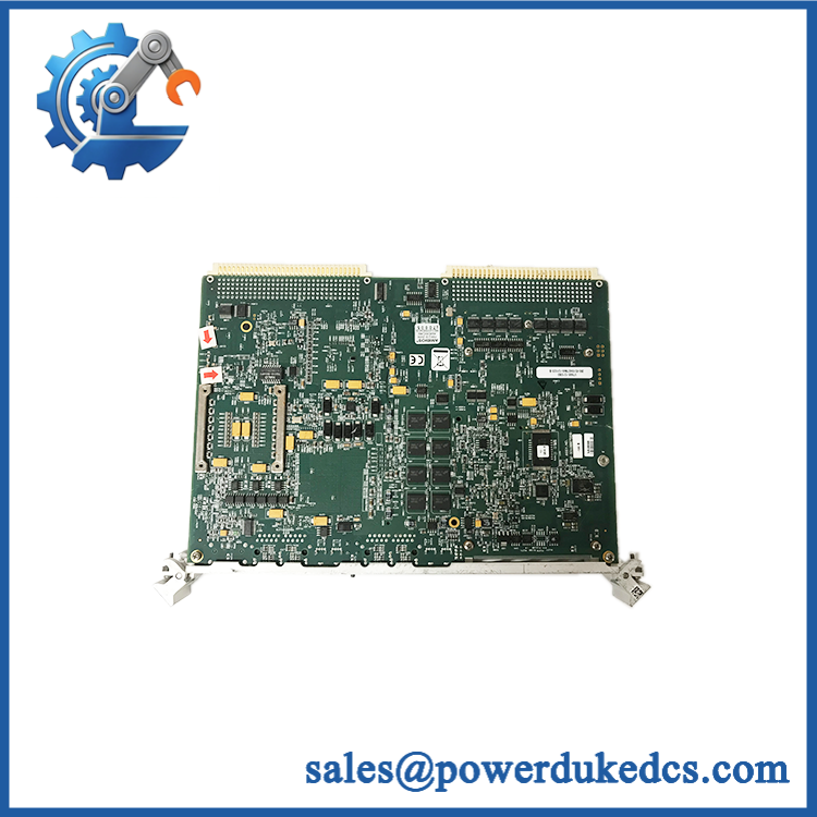
GE BK698CPA15B0
Application Scenarios & Pain Points
For a legacy VME control cabinet, a failed processor can stop the entire system even when all field I/O remains intact. The BK698CPA15B0 is therefore a system-level spare rather than a routine channel replacement.
In embedded industrial control applications, provides the controller with access to the shared VME backplane and associated I/O boards. The exact transfer modes and software architecture depend on the particular hardware implementation.
During a legacy migration project, the application image can become more important than the processor board itself. A replacement without the correct firmware, boot media, hardware configuration, or application files may power up normally but still fail to return the machine to service.
For systems using serial or Ethernet communications, interface configuration should be recorded before removing the original unit. Secondary records associate the with RS-232, RS-485, and Ethernet interfaces, but those claims need confirmation from the actual hardware revision.
At a 50°C+ cabinet ambient, thermal margin deserves specific attention. Passive or board-level cooling assumptions should never replace the original chassis airflow and thermal design requirements.
🚨 Common Error Codes & Diagnostic Symptoms
The is a controller board, and a reliable GE-specific diagnostic-code table for this exact part was not located. The following symptoms are therefore system-level diagnostic indicators rather than guaranteed board fault codes.
Symptom/Code: No normal power-up or no board indication → Diagnosis: Possible causes include missing rack power, poor card seating, damaged VME connector contacts, or internal controller failure. → Action: Verify the rack supply and connector condition first; replace the module if the fault follows the board.
Symptom/Code: Controller not recognized by the host system → Diagnosis: Possible causes include incorrect rack/slot configuration, backplane communication failure, incompatible hardware revision, or corrupted firmware/application files. → Action: Compare the replacement hardware and configuration with the original system before condemning the module.
Symptom/Code: Communication timeout after controller replacement → Diagnosis: Network address, serial parameters, application drivers, firmware, or interface hardware may differ between the original and replacement units. → Action: Record the original communications configuration and validate it on the replacement before further hardware substitution.
🚨 Cross-Reference & Lifecycle Migration
The should be treated as a configuration-specific VME controller.
Current secondary records associate the part with controller applications, while other listings use generic GE Fanuc controller terminology. No authoritative source located during this verification establishes a direct-drop-in successor or predecessor for the exact catalog number.
Do not substitute another GE VME board merely because:
- it fits the same VME slot;
- it carries a similar processor;
- it has similar Ethernet ports;
- or the supplier describes it as a “VME controller.”
The correct comparison must include the VMEbus interface, processor architecture, memory configuration, rear-I/O arrangement, firmware/BIOS, operating system, application image, and chassis compatibility.
Firmware
Firmware is relevant for this type of controller. The available records do not establish a single firmware revision for every , so the installed unit should be checked before replacement.
For legacy systems, preserve the existing:
firmware/BIOS + application image + hardware configuration + communication parameters.
Lifecycle Status
Legacy / limited-availability. Current specialist suppliers still list the exact , while some records identify it as obsolete. Availability therefore depends largely on existing inventory rather than a predictable standard production cycle.
For buffer stock, maintain a complete configuration record rather than storing the item under the generic term “GE VME CPU.”
Field Engineer’s Tech Notes
Warning 1 — Verify the VME connector before insertion.
Do not force the board into the rack. A damaged VME connector can produce intermittent bus faults that look like processor failure. Inspect the card guides, extraction hardware, and connector contacts first.
Warning 2 — Capture the existing software state before replacement.
A controller that reaches the BIOS or power-up screen is not necessarily a valid replacement. Record firmware, boot media, application image, communication settings, and installed memory before removing the original unit (this can save a lengthy recommissioning cycle).
Strict QA & Testing SOP
Step 1 — Identity inspection
Verify , serial number, revision, PCB assembly number, and every secondary label.
Step 2 — Physical inspection
Inspect the PCB, VME connectors, card ejectors, mounting hardware, heat-producing components, memory devices, and rear connectors.
Step 3 — Connector inspection
Check the VME contacts for oxidation, contamination, bent pins, or mechanical deformation.
Step 4 — Configuration documentation
Record memory configuration, firmware/BIOS information, jumpers, switches, storage media, and communications hardware.
Step 5 — Controlled power test
Install the board in a compatible VME test rack. Verify supply voltage before insertion and monitor current during startup.
Step 6 — POST/boot verification
Record board initialization, memory recognition, BIOS behavior, storage detection, and diagnostic messages.
Step 7 — VMEbus test
Use a known-good VME test environment to verify bus access, address mapping, interrupts, and communication with a compatible VME test board.
Step 8 — Serial/Ethernet testing
Where the actual board contains these interfaces, verify RS-232, RS-485, and Ethernet operation against the documented configuration.
Step 9 — Application test
Boot the approved software image and confirm that the application recognizes the expected VME I/O resources.
Step 10 — Continuous test
Run the controller under representative processing and I/O activity while monitoring supply stability and temperature.
Step 11 — Configuration capture
Save firmware information, BIOS settings, application image information, and communications parameters.
Step 12 — Final preservation
Package the board in ESD shielding material with rigid protection around the VME connector and card edges.
Test videos are available for qualifying inventory when pre-shipment evidence is required.
Buyer’s FAQ
Q1. Can I hot-swap the ?
Do not assume live replacement is permitted. Although VME systems can support hot-swap architectures in some applications, that capability depends on the specific chassis, backplane, controller hardware, and software design.
For routine maintenance, use the approved system shutdown and card-removal procedure.
Q2. How do I verify a New Original unit?
Request photographs of the , including the complete nameplate, serial number, revision, PCB assembly marking, connector area, and installed memory/storage hardware.
Because current public records contain conflicting technical descriptions, the physical unit should be the primary identity evidence rather than a generic supplier photograph.
Q3. What warranty should be specified?
Warranty is supplier-specific for this legacy controller. Current secondary listings advertise different coverage depending on whether the unit is New Original, New Surplus, repaired, or refurbished.
The purchase order should clearly state inventory condition, functional test status, warranty period, and return conditions.
Q4. Does the include the latest firmware?
There is no reliable evidence that every carries the same firmware. The installed firmware/BIOS should be captured from the actual unit before commissioning.
For replacement stock, request the firmware revision, memory configuration, boot medium, and application compatibility information rather than accepting a generic “latest firmware” statement.
Asset-Control Note
GE is a legacy GE Fanuc controller module, but public technical records currently disagree on several important electrical and mechanical parameters.
For controlled procurement, the asset record should contain the full part number, physical nameplate photograph, revision, serial number, VME rack type, memory configuration, firmware/BIOS version, storage media, communications interfaces, COO evidence, QA test record, and actual packed weight.
Do not use unverified web dimensions or power ratings as cabinet-design data for this part.











 Start Chat


