

Description
- Model: CT11T7F10PN1
- Additional Identification: PMC676RCTX V2.3 / 01 16 / C1145 / CR11 V2.X
- Brand Reference: GE
- Series: PMC676RCTX / CR11 V2.X
- Part Type: Industrial embedded interface / control module
- Core Function: Provides high-speed host-system interfacing and digital data exchange for the associated embedded industrial-control platform.
- Key Specs: Secondary commercial records report a PCI-X class host interface, RJ45 Ethernet connectivity, 32-bit processing architecture, configurable digital and analog I/O, and a 24 VDC supply. These figures should be treated as identification aids until confirmed against the physical assembly and original manufacturer documentation.
Product Introduction
The CT11T7F10PN1 marking is associated in current industrial listings with PMC676RCTX V2.3, together with the strings 01 16 C1145 and CR11 V2.X. Available records describe the assembly as an industrial embedded interface module intended for high-speed data exchange with a host control platform.
There is an important identity-control issue here. Public commercial sources disagree on the exact architecture: one record describes PMC676RCTX as a high-performance PMC digital I/O module with PCI bus characteristics, while another gives a broader controller description with Ethernet, RS-485, Modbus, memory, and mixed I/O figures. Those differences are too large to normalize into a single certified specification (retain the actual nameplate and board markings as the primary procurement reference).
Core Technical Specifications
| Parameter | Value |
|---|---|
| Manufacturer / Brand Reference | GE |
| Exact Marking | CT11T7F10PN1 |
| Module Identification | PMC676RCTX V2.3 |
| Additional Marking | 01 16 C1145 |
| Architecture Reference | CR11 V2.X |
| Product Type | Embedded industrial interface / control module |
| Host Interface | PMC / PCI-family interface reported |
| PCI Speed | 64-bit / 66 MHz reported by one secondary source |
| Processing Architecture | 32-bit processor architecture reported by one commercial source |
| Digital Inputs | 16 points reported by one commercial source |
| Digital Outputs | 16 points reported by one commercial source |
| Analog Inputs | 8 points reported by one commercial source |
| Analog Outputs | 4 points reported by one commercial source |
| Ethernet | 2 × 10/100 Mbps reported |
| Serial Interface | 2 × RS-485 reported |
| Protocols | Modbus RTU/TCP reported |
| Input Supply | 24 VDC ±10% reported |
| Reported Memory | At least 128 MB RAM and 512 MB Flash reported by one source |
| Reported Operating Temperature | -20°C to +60°C |
| Reported Humidity | 5%–95% RH, non-condensing |
| Reported Protection Rating | IP20 |
| Reported Dimensions | 220 × 160 × 80 mm |
| Reported Weight | Approximately 1.2 kg |
| Software Environment | GE Proficy Machine Edition reported by one source |
| Certification Claims | CE / UL / CSA reported by one secondary source |
| Firmware Revision Reference | V2.3 |
| Lifecycle | Legacy / configuration-dependent |
The values above come from conflicting secondary commercial records and should not be represented as OEM-certified specifications. In particular, the reported I/O channel count, memory, communications, dimensions, weight, and software environment are not consistently documented across the available sources.
For freight planning, use the actual unit measurement and weighed gross package. For engineering release, use the physical nameplate and the applicable system drawing.
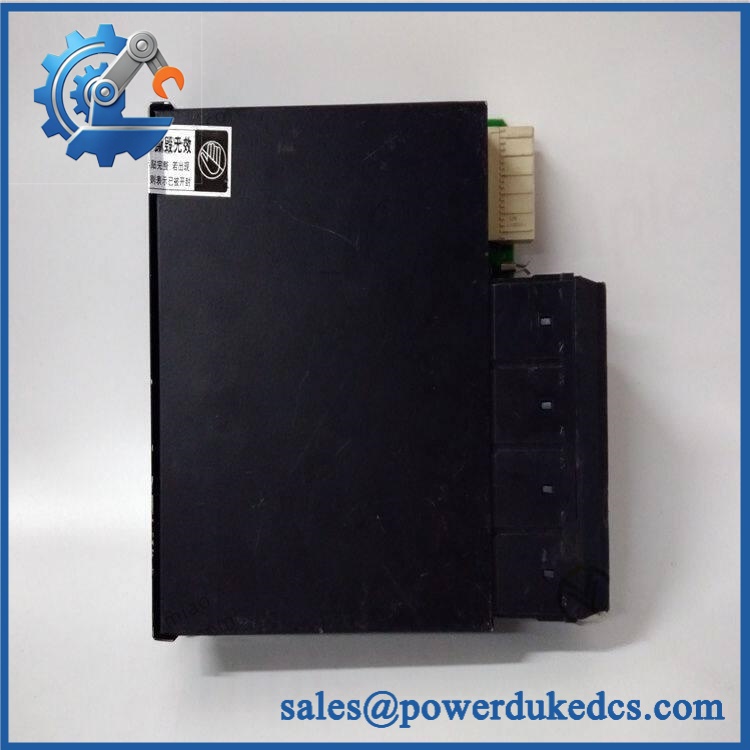
GE CT11T7F10PN1
Application Scenarios & Pain Points
Micro-case — the replacement powers up but the host system does not recognize the board. A mismatch between the physical interface standard, carrier board, firmware revision, or configuration can produce a hardware-looking failure even when the replacement electronics are functional.
Within embedded industrial-control platforms, the PMC676RCTX designation is associated with a high-speed host interface and configurable I/O architecture. Such a module can sit much closer to the host processor than a conventional field I/O card, so carrier compatibility must be established before energization.
For systems using Ethernet and serial communications, a communication failure should be separated into physical-link, protocol, and module-level tests. One commercial listing reports dual 10/100 Mbps Ethernet and dual RS-485 interfaces, while another source emphasizes the PMC/PCI side of the device.
At cabinet temperatures near 50°C, thermal verification becomes important because one secondary specification reports operation to approximately +60°C. The exact limit should be confirmed against the applicable revision before deployment.
🚨 Common Error Codes & Diagnostic Symptoms
No reliable manufacturer-issued numerical error-code list for CT11T7F10PN1 / V2.3 was identified in the reviewed public material. Diagnosis should therefore begin with physical and system-level symptoms.
Symptom/Code: Host processor does not enumerate the PMC module → Diagnosis: Possible carrier incompatibility, connector damage, PCI/PMC interface problem, incorrect power, or incompatible firmware/configuration. → Action: Verify the carrier and interface standard first; replace the module only after the external platform is confirmed healthy.
Symptom/Code: Ethernet link present but application communication fails → Diagnosis: Possible IP configuration, protocol mismatch, firmware incompatibility, or internal communication-interface fault. → Action: Check link status, address/configuration, and protocol settings before replacing the board.
Symptom/Code: Several I/O channels fail simultaneously → Diagnosis: A common supply, interface, FPGA/logic section, or carrier connection may be affecting multiple channels. → Action: Verify field power and host communication, then isolate the module under controlled test conditions.
🚨 Cross-Reference & Lifecycle Migration
Cross-Reference
The available records establish the strongest identity relationship as:
CT11T7F10PN1 ↔ V2.3 / CR11 V2.X
However, no reliable OEM document was found that proves a direct drop-in replacement from another PMC676 or CR11 revision. Similar designations should therefore be treated as related identifiers, not automatic substitutes.
Before approving a replacement, verify:
- Exact CT11T7F10PN1 marking
- revision
- revision
- Carrier-board model
- Connector arrangement
- Firmware/software revision
- I/O configuration
- Host-system compatibility
Firmware Requirement
Firmware matching should be treated as a controlled requirement.
The physical marking includes V2.3, which may identify a hardware or software revision. One secondary source explicitly describes V2.3 as a version requiring compatibility with the host system. Do not overwrite or update firmware merely because a newer image exists; first compare it with the installed system baseline.
Lifecycle Status
Status: Legacy / Configuration-Controlled
The item appears primarily in legacy industrial spare-parts channels rather than clearly documented current-production catalogs. For buffer-stock planning, retain the complete + V2.3 + V2.X identity as one controlled asset record.
Field Engineer’s Tech Notes
Warning 1 — Verify the carrier board before insertion.
A PMC-style module depends on the host carrier for mechanical and electrical compatibility. Do not force the board into a carrier simply because the connector geometry looks similar. Check the carrier model and interface specification first.
Warning 2 — Preserve every revision marking.
The string V2.3 01 16 C1145 V2.X should remain in the maintenance record. Do not shorten the identification to “” (that can erase information needed to distinguish hardware revisions during a future outage).
Strict QA & Testing SOP
Step 1 — Identity verification
Record , , V2.3, 01 16, C1145, and V2.X exactly as marked.
Step 2 — Physical inspection
Check the PCB, carrier connector, mounting edge, labels, shielding, component bodies, and any heatsink or mechanical retaining hardware.
Step 3 — Connector inspection
Inspect the PMC interface and any RJ45 or serial connectors for bent contacts, oxidation, contamination, or mechanical damage.
Step 4 — ESD-controlled handling
Use a grounded ESD workstation and shielding packaging while the module is outside its protective enclosure.
Step 5 — Power verification
Confirm the actual module supply from the approved host-system documentation. Do not apply the reported 24 VDC ±10% value from a secondary listing to an unknown revision without verification.
Step 6 — Host-interface test
Install the unit in a known-good compatible carrier and verify proper module detection and initialization.
Step 7 — Communication test
Where applicable, verify Ethernet and RS-485 interfaces using controlled test equipment and a known-good configuration.
Step 8 — I/O verification
For configurations documented with mixed digital and analog channels, exercise representative inputs and outputs and record measured results. Do not assume every variant has the same channel population.
Step 9 — Firmware verification
Record the actual V2.3-related revision information and compare it with the target system baseline.
Step 10 — Extended operation
Run the assembly under controlled load while monitoring for communication loss, resets, abnormal temperature, or intermittent I/O behavior.
Step 11 — Final inspection
Recheck the connectors, board surface, label condition, and mounting hardware after testing.
Step 12 — Documentation and packaging
Record test results, photographs, serial/date information, revision markings, and final physical condition. Package the board in ESD shielding material with rigid protection.
Test videos are available for applicable units after successful testing on a compatible host platform.
Buyer’s FAQ
Can I hot-swap the ?
Do not assume hot-swapping is permitted. A PMC-style embedded module normally depends on its host carrier and system power state, so removal can affect the host computer or control platform. Follow the installed system’s approved maintenance procedure.
How do I verify a New Original unit?
Request photographs of the actual board, including the complete , V2.3, V2.X, and other visible identification markings. Also verify the carrier interface and connector layout before accepting the part.
What HS tariff code should be used?
The final tariff classification depends on the verified function of the actual assembly and the importing country’s tariff schedule. Because the available records describe the unit in different ways, first establish whether the shipment is being declared as an embedded computer/PMC module, industrial controller, or I/O interface.
Have the importing-country customs broker confirm the final national tariff classification.
Does the module include the latest firmware?
Do not assume that it does. The physical marking includes V2.3, but the correct firmware depends on the host platform and approved configuration. Record the actual revision before commissioning and compare it with the installed system baseline.
What warranty should I expect?
Warranty depends on the supplier’s written terms and the unit’s condition category. For this legacy/configuration-sensitive hardware, obtain the warranty period, functional-test scope, actual-unit photographs, exact revision information, and return conditions before purchase. A third-party warranty should not be represented as a GE factory warranty unless separately documented.











 Start Chat


