

Description
- Model: GE CT7P70500470CW24
- Brand: GE / General Electric
- Series: Exact GE product family not reliably established from primary documentation
- Part Type: Industrial controller / control module according to current secondary parts records
- Core Function: Described in current supplier records as a GE industrial control module intended for control and data-processing applications.
- Key Specs Reported by Secondary Sources: 24 VDC supply, approximately 32 KB user memory, up to 4K I/O, claimed 8 digital inputs / 4 digital outputs, and serial/Ethernet interfaces. These values require physical-unit and OEM-document verification before engineering use.
- Critical Identity Note: Public records are inconsistent. One database places in a GE “motion control module” category, while another associates the number with a low-voltage AC contactor listing. This conflict makes exact hardware identification essential.
Product Introduction
A legacy control cabinet can contain a module whose catalog number is easy to recognize but whose technical documentation has largely disappeared from public circulation. is one such case. Current industrial spare-parts records describe it as a GE controller module, but the public data set does not provide a reliable OEM manual or product drawing that conclusively establishes the exact controller family.
That documentation gap matters during replacement. One current supplier record attributes 24 VDC supply, 32 KB user memory, 4K I/O capability, 8 DI/4 DO, RS-232, RS-485, and Ethernet to the part, while another commercial database associates the same catalog number with a completely different product category. These contradictions mean that the figures below should be treated as secondary reference information rather than certified GE specifications. (For a shutdown-critical asset, the physical label and host-system drawing should take precedence.
Core Technical Specifications
| Parameter | Value |
|---|---|
| Manufacturer | GE / General Electric |
| Catalog Number | |
| Hardware Description | Industrial controller / control module in current secondary records |
| Exact GE Product Family | Not reliably verified |
| Reported Supply Voltage | 24 VDC |
| Reported Supply Tolerance | 18–32 VDC |
| Reported User Memory | 32 KB |
| Reported I/O Capacity | Up to 4K I/O points |
| Reported Digital Inputs | 8 |
| Reported Digital Outputs | 4 |
| Reported Serial Interfaces | RS-232 / RS-485 |
| Reported Ethernet | Yes |
| Reported Protocol Support | Modbus RTU/TCP claimed by one supplier; not independently verified |
| Reported Operating Temperature | −20 to +70°C in one supplier record |
| Reported Humidity | 0–95%, non-condensing in one supplier record |
| Reported Dimensions | Approx. 150 × 100 × 50 mm |
| Reported Weight | Approx. 0.5 kg |
| Reported Protection | IP20 claimed by one supplier record |
| Firmware | Exact firmware architecture not verified |
| Power Dissipation | Not verified |
| Heat Dissipation | Not verified |
| Mounting Method | Rack / cabinet installation claimed by secondary records; exact mechanism not verified |
| Certification | Exact certification for this part not verified |
| Lifecycle | Legacy / documentation-limited |
The 24 VDC, 32 KB, 4K I/O, 8-input/4-output, communication-interface, dimensions, weight, and environmental figures above are reproduced only as reported secondary specifications. There is no sufficiently authoritative GE document in the accessible public record to certify them for .
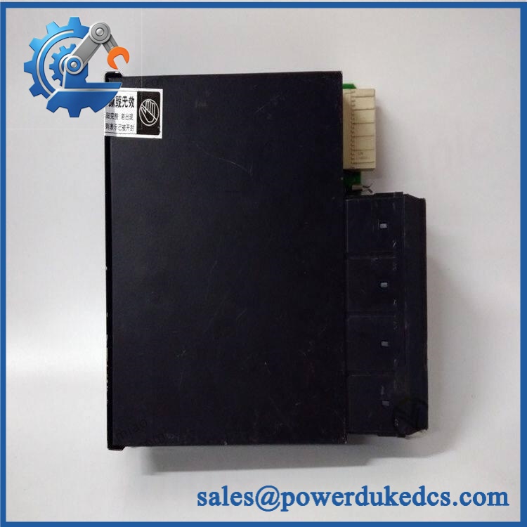
GE CT7P70500470CW24
Application Scenarios & Pain Points
Micro-case — controller replacement: A machine controller stops communicating with the surrounding control system after a power disturbance. Once the 24 VDC supply, field wiring, and communication path are checked, a known-good can be used as a controlled substitution test.
For legacy industrial automation cabinets, secondary records associate the module with control, logic processing, and data-management functions. The same records also claim support for RS-232, RS-485, and Ethernet interfaces, though the exact electrical implementation remains unverified.
In power and process equipment, a compact 24 VDC controller can serve as an interface between supervisory logic and field devices. The claimed 8 digital inputs and 4 digital outputs would make such a configuration suitable for discrete status and command handling, but those channel counts must be confirmed on the actual unit before wiring.
For maintenance warehouses, the greater problem is not simply electronic aging. It is catalog ambiguity. A database currently places this exact number alongside a low-voltage AC contactor entry, which means procurement personnel should not rely on a generic text-only catalog search when approving a replacement.
At 50°C+ cabinet temperatures, thermal verification becomes important if the secondary operating range of −20 to +70°C is applicable. That environmental value remains unverified by a primary GE specification for this exact part.
🚨 Common Error Codes & Diagnostic Symptoms
No authoritative GE service manual establishing -specific numerical error codes was located. The following are therefore diagnostic symptoms rather than official code definitions.
Symptom/Code: Controller fails to initialize after verified 24 VDC power is applied → Diagnosis: Possible internal regulator, processor, memory, or backplane-interface failure; an external power-quality problem must be eliminated first → Action: Measure the actual supply under load and substitute a verified module when the fault follows the .
Symptom/Code: Communication lost while field supply remains stable → Diagnosis: Possible serial/Ethernet interface fault, configuration mismatch, connector problem, or internal controller failure → Action: Test the communication path with a known-good cable and configured peer device, then replace the module if the interface fault remains localized to the controller.
Symptom/Code: Digital status inputs or outputs become intermittently unavailable → Diagnosis: Possible connector degradation, internal I/O circuitry fault, unstable 24 VDC supply, or host-configuration problem → Action: Test each channel with controlled signals and replace the module only after the field wiring has been ruled out.
🚨 Cross-Reference & Lifecycle Migration
Exact Part Identity
The strongest available description is:
GE — Industrial Controller / Control Module
Current secondary sources attribute several controller functions to the number, including 24 VDC operation, 32 KB memory, 4K I/O, and mixed digital/communications interfaces.
However, the available public records are contradictory. One current database lists the exact number in a GE motion-control context, while the same number also appears in a product list associated with a low-voltage AC contactor. No direct drop-in replacement should therefore be declared from online catalog data alone.
Previous Revisions / Replacements
No reliable GE revision matrix was found for . No evidence was established for a direct A/B/C revision replacement, an approved successor number, or a documented supersession path.
Before substitution, compare the physical assembly against the removed unit:
- Complete catalog number
- Hardware revision
- Connector arrangement
- Mounting method
- Host-system model
- I/O count and signal type
- Supply voltage
- Communications interface
- Firmware or software requirements
Firmware Requirement
The available records do not establish a standalone firmware package for this exact number.
One supplier describes the unit as a controller with programmable logic and communications functions, but does not identify a GE firmware file, firmware revision, or approved flashing procedure. Therefore, firmware flashing should not be assumed to be required—or even supported—until the host system and physical hardware revision are identified.
Lifecycle Status
Lifecycle: Legacy / documentation-limited.
Current availability appears to come primarily from specialist industrial spare-parts channels rather than a clearly documented active GE product family. For critical assets, maintain exact-part photographs and host-system compatibility information alongside the physical spare.
GE CT7P70500470CW24
Field Engineer’s Tech Notes
First warning: verify the catalog number directly on the hardware. The public market contains contradictory descriptions for . Never approve a replacement merely because a vendor’s web page calls it a GE controller. (Take a straight-on photograph of the nameplate and every board-level marking before removal.)
Second warning: confirm the power supply before bench testing. A secondary source reports 24 VDC with an 18–32 V tolerance, but that specification is not independently confirmed by an authoritative GE datasheet for this exact number. Do not apply power based solely on a reseller description.
Keep ESD protection in place when handling the PCB or exposed connector surfaces.
Strict QA & Testing SOP
1. Inbound identity verification
Confirm on the physical assembly. Record every GE marking, serial/date code, hardware revision, connector label, and factory sticker.
2. Documentation matching
Compare the physical unit with the customer’s original photographs, cabinet drawing, BOM, and removed assembly. Resolve any discrepancy before energization.
3. Mechanical inspection
Inspect the housing, mounting points, card guides, connectors, terminal blocks, and PCB for cracks, corrosion, contamination, or mechanical damage.
4. Electrical pre-check
Verify supply polarity and measure resistance on appropriate power paths before applying voltage. Use only the host system’s documented electrical limits.
5. Controlled power-up
Apply a current-limited laboratory supply only after the required input voltage has been established from reliable documentation or the installed system.
6. Status and startup test
Observe all available LEDs, startup sequence, processor status, and fault indications. Compare against a known-good reference.
7. I/O simulation
Where the actual hardware confirms digital I/O functionality, exercise each input and output independently using safe, isolated test equipment.
8. Communications test
Test the actual fitted interfaces one at a time. Verify the configured protocol, address, baud rate, parity, Ethernet parameters, or other settings only where confirmed by the host documentation.
9. Memory/configuration test
If the controller exposes user memory or configuration data, verify read/write behavior according to the applicable GE procedure. Do not modify the original application program during a spare qualification test.
10. Thermal observation
Run the unit under representative load and monitor for abnormal heating around power regulators, communication circuitry, and connector areas.
11. Extended operational test
Observe the unit for intermittent resets, communication loss, I/O instability, and unexpected status changes.
12. Final packaging
Place the approved controller in ESD shielding packaging, protect all connectors, add impact cushioning, and retain the complete QC record.
Test videos are available when live functional testing is performed and visual evidence is required for procurement approval.
Buyer’s FAQ
Is definitely a GE PLC CPU?
The available public evidence is not strong enough to make that statement conclusively. Current industrial-parts records call it a controller module and report PLC-like specifications, but another commercial database categorizes the same number differently. The physical nameplate and host-system documentation should be treated as the controlling evidence.;
Can I hot-swap this module?
Do not assume so. The exact architecture and electrical installation procedure have not been reliably established. Unless the applicable GE system documentation explicitly permits energized removal and insertion, isolate the equipment and follow the plant’s electrical safety procedure.
How do I verify New Original authenticity?
Request photographs of the actual , including the complete label, PCB markings, connectors, revision information, and packaging. For a legacy part with inconsistent online descriptions, the physical identification record is particularly important.
What warranty should be specified?
State the exact condition—New Original, New Surplus, refurbished, or repaired—together with the warranty period, functional-test scope, serial-number coverage, and return terms.
For this part, the most important procurement record is + exact hardware revision + physical photographs + host-system reference + verified electrical specification + COO + QC result + packaging condition.











 Start Chat


