

Description
- Model: D20-PS LFDSC143-4000
- GE Part Number: 580-2006
- Brand: General Electric / GE Digital Energy / GE Grid Solutions
- Series: D20/D200 Substation Controller
- Part Type: Chassis-Mounted High-Voltage AC/DC Power Supply
- Core Function: Converts high-voltage station AC or DC input into the regulated rails required by the D20 processor, VME cards, modems, and peripheral I/O.
- Key Specs: 100–300 VDC or 85–264 VAC input, 143 W maximum output, +5 V at 7 A, +12 V at 2 A, -12 V at 1 A, and isolated 24 VDC at 3 A.
Product Introduction
Inside the GE D20/D200 chassis, the D20-PS LFDSC143-4000 is the power-conversion stage that feeds the main processor and installed VME and peripheral hardware. GE documentation identifies 580-2006 as the chassis-mounted D20 power supply with a 100–300 VDC or 85–264 VAC input range and a regulated 24 VDC isolated output, alongside the +5 V, +12 V, and -12 V rails used by the control electronics.
For maintenance teams, the model suffix is worth preserving. Commercial records identify the physical assembly as D20-PS / LFDSC143-4000, while GE’s newer documentation uses the legacy GE catalog number 580-2006 and maps it to the newer smart catalog prefix D20ME-S-C-U-U. That makes 580-2006 a particularly useful identifier when reconciling older D20 cabinets during legacy migration.
Core Technical Specifications
| Parameter | Value |
|---|---|
| Manufacturer | General Electric / GE Digital Energy / GE Grid Solutions |
| Product Family | D20/D200 Substation Controller |
| Product Type | Chassis-Mounted Power Supply |
| Model | D20-PS LFDSC143-4000 |
| GE Legacy Part Number | 580-2006 |
| Supply Class | High-Voltage AC/DC |
| Input Voltage | 100–300 VDC or 85–264 VAC |
| Input Frequency | 47–63 Hz for AC input |
| Maximum Input Current | Approximately 2.4 A maximum, according to unit-specific commercial data |
| Maximum Output Power | 143 W |
| +5 V Output | 7 A |
| +12 V Output | 2 A |
| -12 V Output | 1 A |
| Isolated 24 V Output | 3 A |
| 24 V Output Type | Isolated |
| Mounting | D20 chassis-mounted |
| Installation Orientation | Vertical within the D20/D200 chassis |
| Fuse Quantity | 2 field-replaceable input fuses |
| Fuse Rating | 4 A / 250 V, time-delay, for 580-2006 |
| Fuse Format | 1/4 × 1-1/4 in. / approximately 6.3 × 32 mm |
| Communication Interface | None; power-supply function only |
| Firmware | No user application firmware |
| Memory | None as a user-programmable resource |
| Cooling | Chassis airflow / natural heat dissipation through vented metal enclosure |
| Approximate Unit Weight | About 1.5 kg reported for the power-supply assembly |
| Physical Format | 3U-class D20 chassis plug-in module |
| Exact W × H × D | Verify against the physical unit or GE mechanical drawing |
| Operating Temperature | Exact 580-2006-specific limit should be confirmed from the applicable D20 installation documentation |
| Storage Conditions | Use the applicable D20/D200 environmental specification; protect from condensation |
| Lifecycle | Legacy / discontinued D20/D200 ME hardware |
GE’s installation documentation identifies 580-2006 as a D20 chassis-mounted supply and specifies the four output rails, while its service section confirms the two field-replaceable 4 A / 250 V input fuses.
A current commercial record for the physical D20-PS / 580-2006 assembly reports approximately 1.5 kg. The same source identifies the high-voltage AC/DC construction and 143 W maximum output. Use the actual shipment weight for the commercial invoice and freight booking.
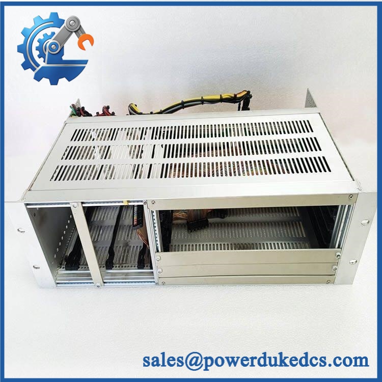
GE D20-PS LFDSC143-4000
Application Scenarios & Pain Points
Micro-case — an entire D20 rack drops offline after a station-battery disturbance. The first measurement should be at the power-supply input and regulated outputs, not at the processor board. A failed 580-2006 can remove several internal rails at once because the supply feeds the D20 main processor, VME cards, modems, and peripheral I/O.
In transmission and distribution substations, the D20/ architecture serves SCADA and substation automation functions, with the power supply providing the internal energy rails needed by the controller hardware. GE currently identifies the older D20/ ME platform as a legacy product with manufacturing discontinued.
For retrofit projects, 580-2006 is particularly useful because GE’s current D20 documentation explicitly maps it to the smart catalog prefix D20ME-S-C-U-U. That gives engineering teams a documented migration path while preserving the legacy part identity in warehouse records.
At sites with elevated cabinet temperatures, inspect the vented metal enclosure, airflow path, fuse area, and output rails during maintenance. Power-supply stress is often visible as discoloration around fuse holders or abnormal rail drift before a complete shutdown occurs.
🚨 Common Error Codes & Diagnostic Symptoms
This is a power-supply assembly, not a programmable controller, so there is no standalone software error-code table.
Symptom/Code: D20 rack completely dead / processor does not start → Diagnosis: Possible loss of AC/DC input, blown input fuse, internal converter failure, or loss of one or more primary output rails. → Action: Verify input voltage and both supply fuses first, then measure the regulated outputs; replace the 580-2006 when the internal supply fault is confirmed.
Symptom/Code: Processor starts but VME or peripheral cards reset repeatedly → Diagnosis: Possible unstable +5 V, +12 V, -12 V, or isolated 24 V output. A marginal rail can cause repeated system initialization without producing an obvious external wiring fault. → Action: Measure the rails under representative load and monitor for voltage drop or ripple before replacing the supply.
Symptom/Code: D20 operates intermittently after thermal rise → Diagnosis: Possible converter component degradation, thermal protection behavior, poor fuse-holder contact, or ventilation restriction. → Action: Check cabinet airflow, fuse contacts, output stability, and temperature; replace the power supply when the fault follows the unit.
🚨 Cross-Reference & Lifecycle Migration
GE Cross-Reference
The most important documented identity is:
D20-PS LFDSC143-4000 → GE 580-2006
GE’s D20/ documentation identifies 580-2006 as the chassis-mounted supply with 100–300 VDC / 85–264 VAC input and 24 VDC isolated output.
Legacy Replacement Relationship
GE’s current D20/ material maps:
580-2006 → D20ME-S-C-U-U
The current brochure describes D20ME-S-C-U-U as the smart catalog representation of the legacy 100–300 VDC / 85–264 VAC, 24 V isolated-output supply.
GE’s technical overview also lists 580-2006 as a drop-in replacement for phased-out 580-0241 and identifies 580-2006 as the replacement supply for phased-out 580-0297 in the corresponding 24 V output configuration. The voltage and output configuration must still be matched to the installed chassis.
Firmware Requirement
No firmware flashing is required for the 580-2006 power supply itself.
The supply has no user application memory or processor firmware. Firmware and boot-image management belong to the D20 processor and related intelligent modules. GE’s spare-parts documentation separately identifies programmed D20 boot-ROM devices, reinforcing that distinction.
Lifecycle Status
Status: Legacy / Discontinued
GE Vernova currently lists the D20/D200ME Substation Controller platform as a legacy product with manufacturing discontinued. GE also directs users toward newer D20MX/D200MX and G500/G100 product families depending on the application.
For buffer stock, maintain the complete / LFDSC143-4000 / 580-2006 identity and record the intended D20 chassis application. This is particularly important because 580-2007 looks similar but provides a different isolated 48 V output.
Field Engineer’s Tech Notes
Warning 1 — Check both fuses before condemning the converter.
GE documents two field-replaceable input fuses on the 580-2006, each rated 4 A / 250 V time-delay. A blown fuse can indicate an upstream fault or an internal supply problem, so simply inserting a new fuse without determining why the original opened is unsafe.
Warning 2 — Do not substitute 580-2007 because the chassis fit looks identical.
Both supplies belong to the same D20 family, but 580-2006 provides isolated 24 VDC at 3 A, while 580-2007 provides isolated 48 VDC at 1.5 A. That output difference can affect connected equipment even though the enclosure and mounting arrangement are similar.
Strict QA & Testing SOP
Step 1 — Identity verification
Confirm the physical markings , , and 580-2006 where present. Record serial/date information and manufacturing-origin markings.
Step 2 — Enclosure inspection
Check the vented metal housing, mounting hardware, front/rear interfaces, fuse section, connector area, and signs of corrosion or impact.
Step 3 — Fuse inspection
Verify both fuse positions and inspect for blown elements, heat discoloration, loose clips, or damaged fuse holders. GE specifies 4 A / 250 V time-delay replacements for 580-2006.
Step 4 — ESD and electrical isolation
Perform inspection under appropriate ESD controls and confirm the unit is fully isolated before continuity measurements.
Step 5 — Input verification
Using an approved D20 test fixture, verify compatibility with 100–300 VDC or 85–264 VAC input. Do not apply an unknown source directly to the unit merely because it is labeled a D20 power supply.
Step 6 — No-load startup
Energize through a controlled source and observe startup behavior, abnormal noise, odor, fuse condition, and output stability.
Step 7 — Output-rail test
Measure +5 V, +12 V, -12 V, and isolated 24 VDC under controlled loading. Record voltage stability under both light and representative load.
Step 8 — Load test
Apply approved loads approaching the documented output currents: 7 A on +5 V, 2 A on +12 V, 1 A on -12 V, and 3 A on isolated 24 V. Do not exceed the test fixture’s approved limits.
Step 9 — Ripple and thermal observation
Measure output ripple with appropriate instrumentation and monitor the metal housing, transformer/converter area, and fuse section for abnormal heat.
Step 10 — D20 rack test
Where available, install the unit in a known-good D20 chassis and verify processor startup, VME-card operation, modem/peripheral behavior, and stable system power.
Step 11 — Power interruption test
Perform controlled input interruption/restart testing according to the approved service procedure and confirm repeatable power-up behavior.
Step 12 — Documentation
Record input source, output measurements, load values, test duration, fuse condition, photographs, serial/date information, and QA status.
Step 13 — Packaging
Protect the vented enclosure, mounting hardware, connectors, and fuse section against impact and contamination. Use an appropriately insulated outer carton for international shipment.
Test videos are available for applicable units tested on a compatible D20 chassis and controlled load fixture.
Buyer’s FAQ
Can I hot-swap the ?
Do not assume that the supply can be removed under power. The 580-2006 is connected to potentially high-voltage AC/DC input and supplies multiple internal rails. GE’s maintenance guidance requires proper power isolation and external overcurrent protection.
How do I verify a New Original unit?
Request photographs of the actual power supply, including the GE part number 580-2006, model marking, fuse section, connector arrangement, serial/date information, and rear enclosure. A generic photograph cannot establish the exact output configuration.
What HS tariff code should be used?
A commercial classification source places 580-2006 within HS 8504.40, the heading used for static converters and power-supply equipment. Treat that as a classification reference only; the final 6-, 8-, or 10-digit tariff code depends on the importing country’s tariff schedule and customs interpretation.
What is the Country of Origin?
A current commercial listing for the exact 580-2006 assembly reports India as the manufacturing location, while D20 system documentation identifies the product as GE equipment. COO should be supported by the actual physical marking or supplier/manufacturer origin documentation before it is placed on a customs declaration.
Does this power supply include the latest firmware?
No. The 580-2006 is a power-conversion assembly and has no user application firmware. Software and boot-image revisions belong to the D20 processor and intelligent communication modules.
What warranty should I expect?
Warranty depends on the supplier’s written commercial terms and the unit condition. For legacy D20 hardware, obtain the warranty period, load-test evidence, actual unit photographs, fuse condition, serial information, and return requirements before purchase. A third-party warranty should not be represented as a GE factory warranty unless separately documented.











 Start Chat


