

Description
- Model: GE D20C PANEL
- Brand: GE / GE Grid Solutions
- Series: D20/D200 Substation RTU
- Part Type: D20C Combination I/O panel assembly
- Core Function: Combines distributed digital status acquisition and control outputs in one D20 peripheral, with optional analog-input or analog-I/O daughter boards.
- Standard I/O: 16 digital inputs + 8 control outputs.
- Optional I/O: Either 16 analog inputs or 8 analog inputs + 8 analog outputs through plug-in daughter boards.
- Physical Assembly: Approximately 19 × 5.25 × 2.5 in; GE documentation treats the D20C as an assembled WESDAC/WESTERM peripheral rather than a single modern PLC card.
Product Introduction
In a D20/D200 substation RTU, the D20C PANEL occupies the distributed I/O layer between field wiring and the main D20/D200 processor. The combination architecture is intended for applications with relatively small point counts while retaining local processing. GE documents the standard D20C as 16 digital inputs and 8 momentary or dual-function trip/close control outputs, with optional analog expansion.
Physically, the assembly consists of separate WESDAC logic and WESTERM termination sections. Field wiring terminates on the WESTERM side, while the WESDAC electronics handle data acquisition, processing, addressing, and communication to the D20 main processor. The two D.20 communication ports support redundant or daisy-chain arrangements (useful when a substation has distributed I/O cabinets).
Core Technical Specifications
| Parameter | Value |
|---|---|
| Manufacturer | GE / GE Grid Solutions |
| Product | D20C Combination I/O Panel |
| Product Family | D20/D200 |
| Hardware Type | Combination I/O peripheral assembly |
| Standard Digital Inputs | 16 |
| Standard Control Outputs | 8 |
| Control Output Type | Momentary or dual-function trip/close |
| Optional Analog Configuration 1 | 16 analog inputs |
| Optional Analog Configuration 2 | 8 analog inputs + 8 analog outputs |
| Processor | 8-bit Freescale 68HC11 MPU |
| MPU Clock | 3 MHz |
| EPROM | 24 KB |
| Static RAM | 32 KB |
| EEPROM | 512 bytes |
| D.20 Link Ports | 2 |
| Maintenance Port | RS-232, 9600 baud |
| Control Output Contact Rating | 60 W max., 3 A max., 220 VDC max. per Form-C/Form-A contact |
| Contact Duration | Programmable 1–215 ms or 1–215 s, protocol dependent |
| Coil Status Check | Every 500 µs |
| Component Isolation | 1,500 Vrms |
| Dielectric Rating | 1,000 VDC |
| Standard Power | 20–60 VDC |
| Typical Consumption | 5 W |
| Full-Load Consumption | Approximately 11 W with 24 V contact wetting |
| Assembly Size | 19 × 5.25 × 2.5 in |
| Daughter Board Size | 8.5 × 3 in |
| Mounting | D20/D200 RTU panel/chassis architecture |
| Field Termination | Compression, DB25, disconnect, barrier, or isolated-common configurations |
| Standard WESDAC Part | 504-0002 + |
| High-Voltage WESDAC Part | 504-0003 D20CHV |
| Lifecycle | Legacy / Order Book Closed for selected variants |
GE’s technical documentation confirms the processor, clock, memory, I/O configuration, communications, contact ratings, power consumption, and physical dimensions.
The ‘s distributed-processing design uses an on-board microcontroller rather than sending every low-level I/O task directly to the main RTU processor. GE describes D20 peripheral modules as intelligent modules configured as slaves to the D20ME/ME II main processor.
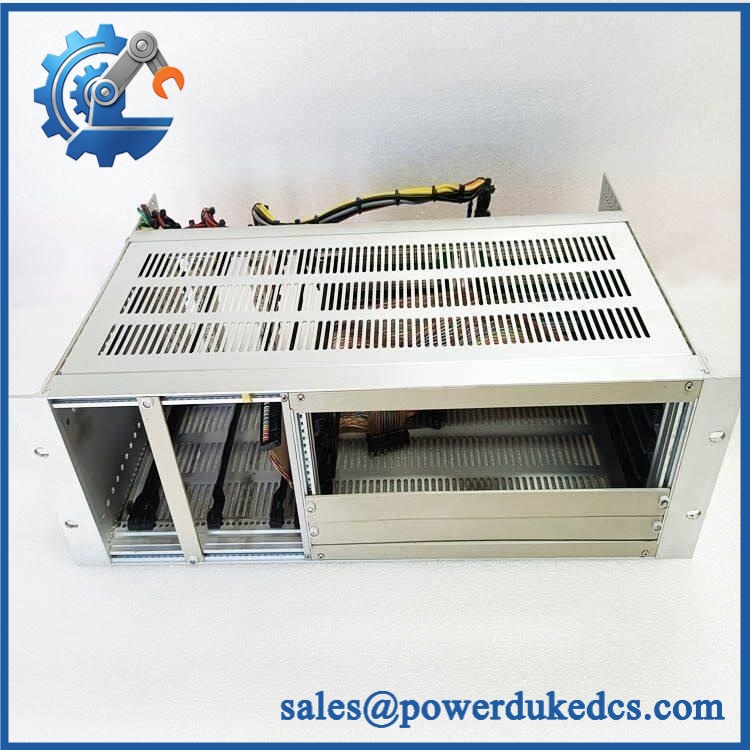
GE D20C PANEL
Application Scenarios & Pain Points
Micro-case — substation RTU expansion: A substation requires additional breaker status points and control commands without adding a completely separate I/O architecture. The combines 16 status inputs and 8 control outputs in one distributed peripheral.
For breaker and switchgear monitoring, the digital inputs acquire field contact states while the control outputs can be configured for momentary or trip/close applications. The maximum documented rating is 3 A and 220 VDC, subject to the exact contact configuration and load.
Where analog measurements are also needed, a D20C1 or D20C2 daughter-board arrangement extends the same peripheral. The available configurations are 16 analog inputs, or 8 analog inputs plus 8 analog outputs.
In distributed substation cabinets, the two D.20 ports support communication redundancy or daisy-chain configurations. The D.20 link uses an HDLC-based protocol over an RS-485 physical layer, with the system supporting distributed peripheral modules over the link
At 50°C+ cabinet temperatures, the has documented environmental qualification at elevated temperature. GE’s published test material includes 55°C dry-heat testing for 16 hours and a 55°C, 100-hour burn-in test for applicable configurations. These are qualification/test conditions, not a universal continuous operating specification.
🚨 Common Error Codes & Diagnostic Symptoms
The does not rely on a single universal numeric error-code convention. GE provides module LEDs and maintenance functions for diagnosis, with the main D20 processor also receiving module status information.
Symptom/Code: ON LED not illuminated → Diagnosis: The module is not receiving its expected supply, or an internal power/control fault is preventing normal startup → Action: Verify the 20–60 VDC supply and field-terminal power path before replacing the .
Symptom/Code: RUN / FAULT indication abnormal → Diagnosis: Possible processor initialization failure, configuration problem, D.20 communications problem, or internal hardware fault → Action: Check D.20 link status and WESMAINT diagnostics first; replace the WESDAC section when the failure follows the module.
Symptom/Code: TX/RX indicators inactive on both D.20 ports → Diagnosis: Possible loss of communication with the D20 main processor, disconnected cable, failed interface, or module not running → Action: Verify both link connections and main-processor status, then test the module on a known-good D20 system.
🚨 Cross-Reference & Lifecycle Migration
Exact Identity
GE PANEL should be treated as an assembly-level description, not a sufficiently specific GE ordering code.
GE’s documented family includes several WESDAC and WESTERM combinations. The standard WESDAC variants include:
- 504-0002 — WESDAC +, 20–60 VDC standard
- 504-0003 — WESDAC D20CHV, 40–150 VDC high-voltage
Termination Options
GE documents multiple termination configurations, including:
- 517-0169 — compression termination
- 517-0180 — D20CD DB25 termination
- 517-0326 — D20CB barrier termination
- 517-0217 — D20CX disconnect termination
- 517-0333 — D20CDI 48 V isolated-common termination
- 517-0263 — D20CDI 130 V isolated-common termination
Those termination panels are not interchangeable from an installation and field-wiring perspective.
Firmware Requirement
The contains local EPROM/RAM/EEPROM and an on-board 68HC11 processor. GE describes the I/O peripheral as receiving configuration and application information from the D20/D200 main processor at startup, while the base application code is stored on the D20/ platform.
Therefore, replacing a does not follow the same firmware procedure as replacing a modern standalone PLC CPU. Configuration and firmware compatibility need to be checked at the D20/ system level, including the WESDAC revision and installed application software.
Lifecycle Status
Lifecycle: Legacy / End-of-Manufacturing for documented variants.
GE’s recent end-of-manufacturing documentation places selected WESDAC + and D20CHV conformal-coated variants in an order-book-closed status. GE also states that repair service may remain available after order closure, subject to material availability, but does not provide an advanced replacement or new spare as part of that repair service.
For buffer stock, identify the complete WESDAC and WESTERM configuration rather than stocking an unspecified “ panel.”
Field Engineer’s Tech Notes
First warning: never separate the WESDAC and WESTERM identities in the warehouse record. The is an assembly with a processing section and a field-termination section. The termination type determines how the existing field wires and interposer connections mate with the replacement.
Second warning: confirm LV versus HV before energizing. The standard 504-0002 + uses 20–60 VDC, while 504-0003 D20CHV uses 40–150 VDC. Similar mechanical construction does not make those power versions interchangeable.
Before removal, photograph the termination wiring and the WESDAC identification label. For legacy RTUs, those two records often save more troubleshooting time than a generic product photograph.
Strict QA & Testing SOP
1. Inbound identity verification
Confirm the actual WESDAC order code, such as 504-0002 or 504-0003, along with the WESTERM termination order code. Do not accept “ PANEL” as the only identification field.
2. Physical inspection
Inspect the WESDAC enclosure, WESTERM panel, card guides, screw terminals, DB25 connectors, disconnect blocks, LEDs, and grounding hardware.
3. Configuration check
Verify whether the assembly is configured for standard digital I/O, 16 analog inputs, or 8 analog inputs + 8 analog outputs.
4. Power verification
Confirm LV or HV input requirements before energization. For the standard , GE specifies 20–60 VDC and approximately 5 W typical consumption.
5. Startup and LED test
Apply controlled power and verify ON, RUN/FAULT, and applicable TX/RX indications.
6. Digital-input test
Exercise all 16 status inputs with isolated test contacts or approved signal sources. Verify state reporting to the D20 main processor.
7. Control-output test
Test the eight output channels individually using an appropriate load. Verify contact operation, timing, and control-output configuration.
8. Analog test
Where fitted, use calibrated analog sources to exercise the daughter-board channels. Verify scaling, accuracy, and channel reporting.
9. D.20 communications test
Connect both D.20 ports where redundancy is required. Verify transmission, reception, module addressing, and communication recovery after a controlled link interruption.
10. Maintenance-port test
Use the 9600-baud RS-232 WESMAINT interface to access approved maintenance functions, including viewing data and forcing control points where the test environment permits. GE documents WESMAINT as the maintenance facility for testing and calibration.
11. Thermal observation
Operate the assembly under representative I/O loading and monitor internal temperature and relay-output behavior.
12. Final preservation
Protect the WESDAC electronics in ESD-safe packaging and secure all WESTERM terminals and connectors against impact. Retain photographs of the entire assembly configuration.
Test videos are available when live functional verification is performed and visual evidence is required for procurement approval.
Buyer’s FAQ
What exactly does “ PANEL” mean?
It is best treated as a combination I/O assembly description, not a complete ordering code. GE documents multiple WESDAC versions and several WESTERM termination options, so the exact replacement requires both sections to be identified.
Can the panel be hot-swapped?
GE’s D20 architecture was designed with modular I/O hardware and maintenance facilities, and certain documentation describes removable peripheral assemblies. However, hot replacement still depends on the exact rack, power arrangement, field circuit, and site procedure. For energized substation equipment, follow the approved D20 maintenance procedure rather than assuming every assembly can be withdrawn live.
How do I verify a New Original assembly?
Request photographs of the WESDAC module and WESTERM termination panel together, including all order codes, revision markings, terminal type, labels, and connectors. A bare “” description does not establish the exact hardware configuration.
What warranty should be specified?
Record whether the assembly is New Original, New Surplus, refurbished, or repaired, together with the warranty period and functional-test scope. Because GE has closed orders for selected variants, document the exact WESDAC and WESTERM configuration in the purchase record.
For long-term asset control, record + WESDAC order code + WESTERM order code + LV/HV version + analog daughter-board option + hardware revision + serial/date code + COO + QC result + packaging condition.











 Start Chat


