

Description
- Model: DS200DMCBG1AED
- Brand: GE / General Electric
- Series: Mark V DS200 / Speedtronic
- Part Type: IOS/DUP Processor Board, commonly described in GE Mark V inventories as a DOS DUP Processor Board
- Core Function: Provides processor and interface circuitry within the Mark V turbine-control architecture, handling board-level communications and control-system processing.
- Key Specs: 3 × 26-pin connectors, 1 × 40-pin connector, 19 jumpers, 2 red LEDs, and a board-mounted reset pushbutton are documented for the DS200DMCBG1A family.
- Hardware Identity: The G1 identifies the board family and standard-coating construction, while the trailing characters identify functional/assembly revisions. The exact AED suffix should remain intact in purchasing and warehouse records.
Product Introduction
A Mark V control cabinet can continue to receive field signals while a processor-board problem disrupts coordination between the control subsystems. That makes the DS200DMCBG1AED a system-level maintenance item rather than a simple terminal or passive interface card.
The board belongs to the GE Mark V turbine control system and is identified as a DMCB processor board in current legacy parts records. The documented DS200DMCBG1A hardware carries three 26-pin connectors, one 40-pin connector, 19 jumpers, two red LEDs, and a reset button. The reset function allows qualified maintenance personnel to restart the board without restarting the complete drive or control system.
For legacy migration work, connector and revision identity matter. Mark V inventories contain numerous DMCB variants, including DS200DMCBG1A, DS200DMCBG1ABA, DS200DMCBG1ABB, DS200DMCBG1ACB, DS200DMCBG1AED, DS200DMCBG1AFD, DS200DMCBG1AGE, DS200DMCBG1AJE, DS200DMCBG1AKG, and DS200DMCBG1ALG. These are not interchangeable merely because the family name is similar.
Core Technical Specifications
| Parameter | Value |
|---|---|
| Manufacturer | GE / General Electric |
| Product Family | Mark V DS200 |
| Exact Model | DS200DMCBG1AED |
| Functional Board Family | DMCB |
| Product Type | IOS/DUP Processor Board / DOS DUP Processor Board |
| Turbine Platform | GE Mark V Speedtronic |
| Board Revision Family | G1 |
| Functional Base Revision | A |
| Connectors | 3 × 26-pin + 1 × 40-pin |
| Jumper Count | 19 |
| LEDs | 2 red LEDs |
| Reset Function | Board-mounted reset pushbutton |
| PCB Coating | Standard / normal coating for G1 family |
| Processor | Exact device type not reliably established from the authoritative material reviewed |
| RAM | Exact capacity not reliably established for this exact AED revision |
| Flash / Nonvolatile Memory | Exact capacity not reliably established |
| Backplane Supply | Mark V system-dependent; exact board-specific supply figure should be taken from the applicable GE documentation |
| Firmware | Mark V system firmware/configuration dependent |
| Mounting | DS200-series Mark V rack/card mounting |
| Field Terminal Blocks | Not the primary field-interface function |
| Cooling | Dependent on Mark V cabinet airflow |
| Operating Temperature | Exact AED-specific value not reliably established |
| Storage Temperature | Exact AED-specific value not reliably established |
| Approx. Shipping Weight | Supplier listings vary; verify the packed unit before freight booking |
| Lifecycle | Legacy / obsolete |
| Typical Application | Gas, steam, and wind turbine control systems |
The connector, jumper, LED, reset-button, and G1-family characteristics are documented for the DS200DMCBG1A family. Current Mark V parts catalogs specifically list DS200DMCBG1AED as a DMCB processor board, but they do not provide enough revision-specific information to assign an exact CPU or memory configuration to AED without risk of overstatement.;
Power and Thermal Note
The board is part of the Mark V internal control architecture, so its power demand should be evaluated as part of the complete DS200 rack and cabinet power budget. A generic 5 V or 24 V value should not be copied from another DS200 board.
Thermal conditions deserve the same caution. The processor card sits among other electronics inside a turbine-control enclosure, and a 50°C+ cabinet environment can reduce margin for aging components, connectors, and power-conditioning circuitry. Use the site’s Mark V thermal design data for final engineering calculations.
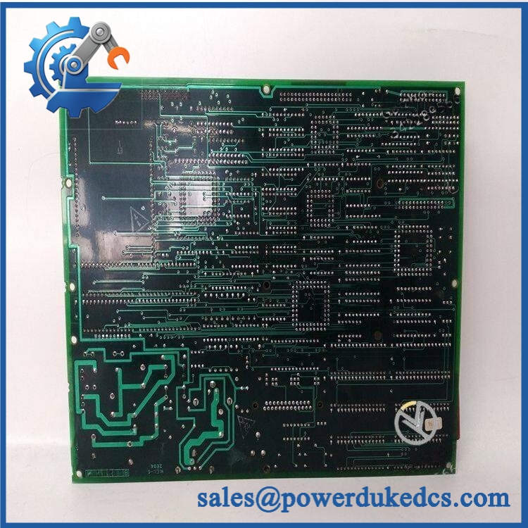
GE DS200DMCBG1AED
Application Scenarios & Pain Points
During a turbine start sequence, an intermittent control-board reset can be mistaken for a field-device problem. The DMCB processor board is part of the Mark V processing architecture, so unexplained processor resets or loss of internal coordination should trigger inspection of board seating, connectors, jumpers, power quality, and the board itself.
For gas-turbine control systems, the Mark V platform was designed for turbine management and control, including compatible gas and steam turbine applications. The DMCB processor family is therefore typically found in a control cabinet rather than in a remote field junction box.
Within legacy steam-turbine installations, processor-board availability can become a maintenance bottleneck because the Mark V architecture is now a mature platform. Exact revision tracking helps prevent an incorrect DMCB variant from entering a critical spare pool.
For wind-turbine control applications, Mark V installations can also contain the DMCB family. The same board-level inspection principles apply: compare the exact connector arrangement, revision, jumper configuration, and installed system location before substitution.
In long-running plants, the reset pushbutton is a useful diagnostic feature. GE-related technical records state that pressing the reset button for approximately three seconds can restart the board and clear its signals without restarting the entire drive/control system. Only qualified personnel should perform that procedure within an approved maintenance sequence.
🚨 Common Error Codes & Diagnostic Symptoms
The DS200DMCBG1AED does not have a standalone fault-code system comparable to a modern PLC I/O module. Most diagnostic evidence is presented through the Mark V control system, board LEDs, processor behavior, and system alarms.
Symptom/Code: Processor board becomes unresponsive / control communication is lost → Diagnosis: Possible causes include a failing DMCB processor, poor board seating, connector contamination, power disturbance, or an internal hardware fault. → Action: Check rack power and physical connections first, then compare behavior with a known-good DMCB board.
Symptom/Code: Board operates intermittently and recovers after reset → Diagnosis: An internal processor lockup, unstable power condition, marginal connector, or aging component may be present. The reset pushbutton can restore operation temporarily, but repeated resets are not a repair. → Action: Capture system alarms and diagnostic evidence, inspect the board and rack, and replace the module if the fault follows it.
Symptom/Code: One or both board LEDs show abnormal status → Diagnosis: The two red LEDs provide local board status information, but their exact meaning must be correlated with the particular Mark V documentation and board revision. → Action: Record the LED state before resetting the board, then consult the correct Mark V diagnostic procedure.
🚨 Cross-Reference & Lifecycle Migration
The sits within a large DMCB processor-board family. Current Mark V parts records list:
- DS200DMCBG1A
- DS200DMCBG1ABA
- DS200DMCBG1ABB
- DS200DMCBG1ACB
- DS200DMCBG1AFD
- DS200DMCBG1AGE
- DS200DMCBG1AJE
- DS200DMCBG1AKG
- DS200DMCBG1ALG
- DS200DMCBG2A
- DS200DMCBG2AKG
These part numbers represent different revisions or board configurations. No reliable source reviewed here establishes a blanket direct-drop-in relationship between and every other DMCB number.
Previous Revisions and Replacement Strategy
The base DS200DMCBG1A is the foundational catalog identifier for this DMCB board family. The additional suffixes identify later functional or assembly revisions. Because the exact AED engineering changes are not documented in the public sources reviewed, do not state that AED is a universal drop-in for A, ABA, ABB, or other revisions.
For procurement, compare:
complete part number + PCB revision + connector layout + jumper configuration + Mark V control-system location.
Firmware
The DMCB is part of the Mark V processor architecture, so system software and firmware compatibility matter. However, the exact firmware image associated with was not reliably established from the sources reviewed.
Do not flash a replacement board simply because a newer image exists. Preserve the existing Mark V software baseline and confirm compatibility before changing any firmware or programmable memory.
Lifecycle Status
Legacy / obsolete. Current specialist inventories continue to list , while the broader DS200 Mark V family is clearly maintained through aftermarket and repair channels rather than current-generation GE production.
For buffer stock, retain the exact AED suffix. A generic DMCB spare should not be released unless the engineering team has documented interchangeability.
Field Engineer’s Tech Notes
Warning 1 — Photograph all 19 jumper positions before removal.
The board contains 19 jumpers, and their configuration can be part of the installed-system setup. Do not assume a replacement board should be left in whatever position it arrives from inventory. Compare the original card against the controlled Mark V drawing first.
Warning 2 — Use the reset button as a diagnostic step, not as a permanent workaround.
The documented reset function can restart the board without restarting the complete drive/control system. If the same board needs repeated manual resets, treat that as fault evidence. Check rack power, connectors, environmental conditions, and board health rather than normalizing the reset procedure.
Strict QA & Testing SOP
Step 1 — Inbound identity check
Verify the complete marking, serial/date information where available, PCB assembly number, and revision markings.
Step 2 — Physical inspection
Inspect the PCB for discoloration, burned components, cracked solder joints, lifted traces, corrosion, contamination, and evidence of unauthorized repair.
Step 3 — Connector inspection
Check all three 26-pin connectors and one 40-pin connector for bent contacts, oxidation, contamination, or mechanical damage.
Step 4 — Jumper documentation
Photograph and record all 19 jumper positions before any power test.
Step 5 — Reset-function inspection
Confirm that the board-mounted reset pushbutton operates mechanically without binding. Do not repeatedly cycle it merely for demonstration.
Step 6 — LED inspection
Verify the two red LEDs illuminate as expected during controlled test conditions. Record the exact startup sequence.
Step 7 — Controlled power test
Install the board in a compatible Mark V test assembly and apply power through the approved rack supply. Monitor startup current and abnormal behavior.
Step 8 — Processor/board initialization
Verify that the control system recognizes the DMCB board and that no immediate processor, communication, or board-level alarm is generated.
Step 9 — System communication test
Exercise the appropriate Mark V internal interfaces and confirm stable communication with the associated control hardware.
Step 10 — Functional test
Use a suitable Mark V simulation or test stand to verify processor operation and representative control-system functions.
Step 11 — Reset test
Under controlled conditions, execute the approved reset procedure and confirm that the board restarts correctly without producing a persistent fault.
Step 12 — Thermal observation
Run the board for an appropriate test interval while monitoring local temperature and checking for abnormal heating around power components, connectors, and processor circuitry.
Step 13 — Final traceability
Record part number, revision, jumper configuration, test-rig model, startup behavior, LED status, reset result, and final QA disposition.
Step 14 — ESD packaging
Place the accepted PCB in an ESD shielding bag with rigid protection around all connector edges. Keep the board flat and prevent pressure on components.
Test videos are available for qualifying inventory when pre-shipment inspection evidence is required.
Buyer’s FAQ
Q1. Can I hot-swap the ?
Do not assume live removal is permitted. This is a Mark V processor board with multiple control-system connections, and the safe procedure depends on the specific cabinet architecture and maintenance method.
Use the approved Mark V isolation procedure and verify the rack is safe before removing the card.
Q2. How do I verify a New Original unit?
Request photographs of the , including the full part number, board revision, all connectors, the 19-jumper area, LEDs, and reset pushbutton.
For New Original procurement, retain the factory packaging and traceability information where available. A generic photograph is not enough to prove that the suffix is AED.
Q3. What warranty should be specified?
Warranty depends on supplier and inventory condition. Current specialist suppliers offer different warranty periods for unused, surplus, repaired, and refurbished Mark V boards.
Specify New Original, New Surplus, repaired, or refurbished explicitly, together with the warranty period and functional-test coverage.
Q4. Does the include the latest firmware pre-loaded?
A reliable AED-specific firmware revision was not established from the sources reviewed. Because this board participates in the Mark V processing architecture, firmware/software compatibility should be checked against the installed system before commissioning.
Capture the existing Mark V software baseline and any board-specific memory or firmware information before replacement.
Procurement & Lifecycle Note
The is a Mark V DMCB IOS/DUP processor board within the family. The board’s documented physical identifiers include three 26-pin connectors, one 40-pin connector, 19 jumpers, two red LEDs, and a reset pushbutton.
For asset control, record the full number, PCB revision, serial/date information, jumper configuration, connector condition, host Mark V cabinet/location, firmware/software baseline, COO, certification evidence, QA result, and storage condition. Do not collapse the part number to the geeric family when issuing or receiving a critical turbine-control spare.











 Start Chat


