

Description
- Model & Brand: DS200DTBAG1AAA | GE General Electric
- Series: Mark V Speedtronic DS200
- Part Type: Digital I/O Terminal Board / Contact Input-Output Termination Board
- Physical Dimensions: Approx. 11.5 × 3.0 in (292 × 76 mm) board envelope
- Estimated Net Weight: Approx. 0.35–0.50 kg, depending on terminal hardware
- Estimated Shipping Weight: Approx. 0.8–1.2 kg with ESD packaging and rigid carton
- What’s in the Box: DS200DTBAG1AAA board; ESD shielding bag; protective packaging; mounting hardware only when explicitly specified
- Terminal Blocks: 2
- Terminal Capacity: Up to 95 signal terminals per block
- Primary Connectors: 2 × 50-pin ribbon-cable interfaces
- Configurable Jumpers: Board-specific jumper configuration; verify the actual revision before installation
- Mounting: Internal Mark V cabinet board assembly
Product Introduction
A Mark V termination board sits directly in the signal path between cabinet wiring and the turbine-control electronics. GE DS200DTBAG1AAA is a Digital I/O Terminal Board used in the Mark V Speedtronic control architecture. Its terminal blocks provide high-density field-wiring termination, while the 50-pin ribbon-cable interfaces connect the board to the corresponding control electronicsides on the board itself; the practical replacement risks are therefore physical and electrical—wrong terminal assignment, incorrect ribbon-cable connection, unsuitable revision, or damaged contacts. The DS200DTBAG1AAA is part of the legacy DS200 family, and current specialist inventory records continue to identify it as a Mark V digital I/O termination board. A like-for-like spare can preserve the installed field wiring and cabinet arrangement (which is useful when a turbine shutdown window is tightly controlled).
Core Technical Specifications
| Parameter | Value |
|---|---|
| Manufacturer | GE General Electric |
| Part Number | DS200DTBAG1AAA |
| Series | Mark V Speedtronic DS200 |
| Functional Description | Digital I/O Terminal Board |
| Functional Acronym | DTBA |
| Product Type | Field signal termination / interface board |
| Board Length | Approx. 11.5 in / 292 mm |
| Board Height | Approx. 3.0 in / 76 mm |
| Terminal Blocks | 2 |
| Terminal Positions | Up to 95 per terminal block |
| Total Terminal Positions | Up to 190 |
| Ribbon-Cable Interfaces | 2 × 50-pin |
| Application | GE Mark V turbine-control system |
| Signal Function | Digital I/O field termination |
| Processor | None |
| Standalone Firmware | None |
| Mounting | Internal Mark V control cabinet |
| PCB Family | DS200 |
| Lifecycle | Legacy / obsolete spare |
| Configuration | Revision-dependent; verify actual PCB markings and jumper arrangement |
The exact DS200DTBAG1AAA identification and Mark V application are supported by specialist DS200 inventory records.
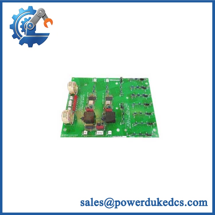
GE DS200DTBAG1AAA
🚨 Global Compliance & Industry Certifications
For compliance purposes, should be classified as an internal Mark V system component. Certification of the complete installation takes precedence over unsupported standalone claims for the PCB.
- CE Mark: No standalone CE declaration specific to was established from the documentation reviewed.
- UL/cUL: No independent UL/cUL listing was established for this exact DS200 board.
- ATEX/IECEx: No standalone ATEX or IECEx certificate was established for .
- Marine Approvals: No -specific DNV, ABS, or Lloyd’s Register approval was established.
- System-Level Compliance: Hazardous-area suitability, EMC performance, grounding, and enclosure requirements depend on the complete Mark V installation.
- EMC Considerations: Digital field wiring should remain routed and terminated according to the approved Mark V cabinet drawings.
Do not transfer certification claims from Mark VI, Mark VIe, or other boards to this specific part. Where a plant operates under hazardous-area certification, an unauthorized board substitution may create a documentation and audit discrepancy.
Verify specific lot certifications with OEM.
🚨 Long-Term Storage & Asset Preservation Guide
Store in an ESD shielding bag. The board contains semiconductor devices and exposed connector interfaces; static discharge can damage components without leaving an obvious physical mark.
Control warehouse humidity. A practical long-term target is below 60% RH, with stable temperature and no condensation cycles. Allow the sealed package to reach ambient temperature before opening after transport from a cold storage area.
Protect the terminal blocks and ribbon connectors from impact. Never stack heavy boards directly against the terminal assemblies. Bent terminals, cracked connector bodies, or recessed contacts can create intermittent faults after installation.
Record the complete board identity before shelving. Photograph the GE label, board revision, connector locations, and any jumpers. Keep the image with the asset record so an engineer can compare the spare against the installed board without opening the ESD package.
Do not use a generic capacitor-reforming interval. No board-specific reforming procedure was established in the documentation reviewed. Controlled electrical inspection before critical deployment is the safer release criterion.
Physical Installation Prerequisites
is an internal Mark V termination board, not a DIN-rail component. It is installed within the GE turbine-control cabinet and connected through its field terminals and internal ribbon interfaces.
Before installation:
- Confirm the host equipment is a GE Mark V Speedtronic system.
- Verify the complete part number and actual board revision.
- Photograph every field-wire termination before disconnecting the existing board.
- Label both 50-pin ribbon cables and record their exact connector positions.
- Inspect terminal screws, insulation barriers, and cable-entry points.
- Examine the 50-pin connectors for bent, recessed, oxidized, or contaminated contacts.
- Record all visible jumpers or configuration links before removal.
- Verify the replacement board’s mounting holes and standoffs match the installed chassis.
- Preserve the original cable routing and separation from high-energy conductors.
- Confirm cabinet grounding and shield termination against approved Mark V drawings.
- Use ESD controls throughout removal and installation.
- Do not impose a generic 50 mm clearance around the board. The Mark V cabinet design determines ventilation and service clearance.
- Perform continuity checks on field wiring before re-energizing the cabinet.
Buyer’s FAQ
Q1. What HS tariff code should be used for ?
A: Final classification depends on the importing country’s tariff schedule and the legal description used at customs. For a dedicated printed-circuit termination component, HS heading 8538 may be considered where it is classified as a part suitable for electrical control equipment. The importer or customs broker should confirm the final country-specific code before shipment.
Q2. Does Country of Origin mean the country where my supplier ships the board?
A: No. COO is determined under the applicable origin rules for the physical board, not merely by its export warehouse. Keep the manufacturer’s origin evidence or supplier declaration, actual board identification, commercial invoice, and Certificate of Origin where required.
Q3. How should I package and insure this board internationally?
A: Use an ESD shielding bag, protect the 50-pin connectors and terminal blocks with rigid cushioning, and immobilize the PCB inside a suitable carton. The actual packed weight should be measured before freight booking because supplier-reported board weights can vary with mounting hardware. For a critical turbine spare, cargo insurance should cover the declared replacement value.
Q4. Does ship with the latest firmware pre-loaded?
A: No. This is a digital I/O termination/interface board, not a standalone processor. Firmware is not normally stored or updated on the board. The important records are the exact board revision, terminal assignment, ribbon-cable positions, and host Mark V configuration.
A: No, not as a routine maintenance operation. The board carries extensive field wiring and internal ribbon connections. Follow the approved Mark V isolation procedure, document every termination before removal, install the replacement under ESD controls, then perform continuity and functional verification before restoring power.











 Start Chat


