

Description
- Model: DS200DTBCG1AAA
- Brand: GE General Electric
- Series: Mark V Speedtronic
- Functional Acronym: DTBC
- Part Type: Contact Output Termination Module / Connector Relay Terminal Board
- Functional Revision: A / A
- Artwork Revision: A
- PCB Coating: Normal coating
- Approximate Dimensions: 10.5 × 6.5 × 2.0 in reported by secondary inventory records; published listings vary, so verify the actual board before freight booking
- Estimated Shipping Weight: 0.91 lb / approximately 0.41 kg in one inventory record; other listings report approximately 0.78–0.91 kg, so the packed shipment should be physically weighed
- Terminal Capacity: 2 terminal blocks, up to 110 signal-wire terminals each
- Relay Outputs: 30 relay positions
- Connectors: JS1–JS8 relay-signal interfaces; J8 power-signal interface; J15/J16 125 VDC contact-output power interfaces
- Jumpers: 10 hardware jumpers
- Typical Mark V Locations: Q11 / Q51; installation is configuration-dependent
- What’s in the Box: DS200DTBCG1AAA board only unless the PO explicitly includes mating cables, terminal hardware, or accessories
- Packaging: ESD shielding bag, connector protection, rigid cushioning, moisture-controlled outer carton
GE/Mark V service records identify DS200DTBCG1AAA as a Contact Output Termination Module, with two large terminal blocks, 30 relay positions, ten jumpers, and dedicated relay/power connectors.
Product Introduction
Structure A — Environmental Hook
Inside an older Mark V turbine-control cabinet, this board is exposed to the same cabinet temperature, vibration, dust, and electrical transients affecting the surrounding termination hardware. The GE DS200DTBCG1AAA is a relay/contact termination assembly rather than an intelligent CPU board. Its job is to terminate and route contact-output signals between Mark V control electronics, relay circuits, and field devices. The documented architecture includes JS1–JS8 for relay signals from the TCRA board, J8 for TCPD-related power signals, and J15/J16 for 125 VDC contact-output power.
For lifecycle management, exact identification matters more than a generic “Mark V terminal board” description. The DS200DTBCG1AAA is an earlier revised version within the DTBC family, and service records identify three A-designation revisions while noting that revision history can affect compatibility. A receiving department should therefore capture the full part number, PCB revision, jumper positions, terminal arrangement, and any associated TCRA/TCPD references before putting the board into strategic spare inventory.
Core Technical Specifications
| Parameter | Value |
|---|---|
| Manufacturer | GE General Electric |
| Part Number | DS200DTBCG1AAA |
| Series | Mark V Speedtronic |
| Functional Acronym | DTBC |
| Product Type | Contact Output Termination Module |
| Alternative Description | Connector Relay Terminal Board |
| Functional Revision 1 | A |
| Functional Revision 2 | A |
| Artwork Revision | A |
| PCB Coating | Normal coating |
| Relay Positions | 30 |
| Terminal Blocks | 2 |
| Terminals per Block | Up to 110 signal-wire positions |
| Hardware Jumpers | 10 |
| Relay Outputs 1–15 | Dry contact or 125 VDC solenoid application |
| Relay Outputs 16–17 | Fused solenoid outputs, including applications such as 20CB/20FD |
| Relay Output 18 | Current-limited output for applications such as 20CF |
| Relay Outputs 19–30 | Dry contacts |
| Relay Signal Connectors | JS1–JS8 |
| Power Signal Connector | J8 |
| 125 VDC Output Power Connectors | J15, J16 |
| Typical Core Location | Q11 / Q51; site-dependent |
| Processor | None |
| User Memory | None; termination/relay hardware rather than an application processor |
| Firmware Storage | None on the termination board itself |
| Power Draw | Primarily determined by connected relay/solenoid loads |
| Heat Dissipation | Load-dependent; relay coil and powered-solenoid circuits determine local thermal loading |
| Approx. Weight | 0.91 lb / 0.41 kg in one inventory record |
| Approx. Dimensions | 10.5 × 6.5 × 2.0 in in one secondary record |
The relay allocation and connector functions above are documented in Mark V service-oriented records. Physical dimensions and weight vary across secondary records, so the actual asset should be measured before export packing or freight quoting.
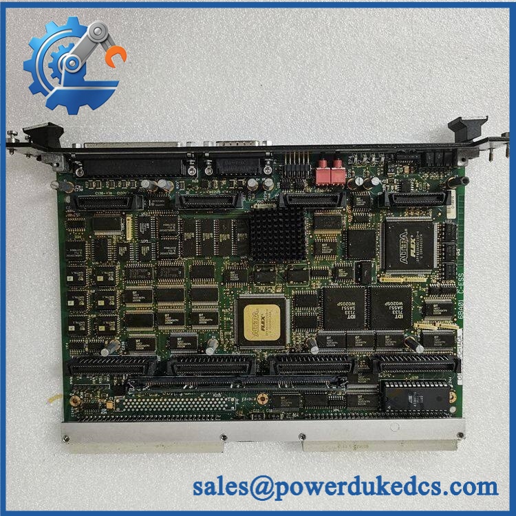
GE DS200DTBCG1AAA
🚨 Global Compliance & Industry Certifications
- CE Mark: Do not assign a standalone CE claim to this PCB without the applicable GE documentation and revision record. The board forms part of a larger Mark V control assembly.
- UL/cUL: No current, revision-specific evidence was established that supports a blanket UL/cUL claim for every unit.
- ATEX / IECEx: Do not assume hazardous-area certification. A Mark V turbine-control cabinet may interface with hazardous-area equipment, but that does not make the terminal board independently certified for hazardous locations.
- Marine approvals: No revision-specific DNV approval was established for from the accessible records.
- Electrical safety: The board can interface with 125 VDC contact-output power, making isolation and de-energization especially important during maintenance. GE service guidance requires removal of all applicable power sources before replacement.
- Audit record: Retain the exact part number, revision, serial/lot information, nameplate photograph, applicable GE drawing, COO, and test report.
Verify specific lot certifications with OEM.
The most important compliance issue here is not a generic certification label; it is proving that the physical board supplied matches the engineered Mark V configuration for which it is being purchased.
🚨 Long-Term Storage & Asset Preservation Guide
Keep the board inside an ESD shielding bag. The has multiple connectors, relay interfaces, terminal points, and hardware jumpers. Repeated handling without ESD control can damage adjoining circuitry or connector contacts even when no damage is visible.
Protect the terminal blocks and jumper field. Do not stack heavy boards over the long terminal edge. The 10 hardware jumpers should remain in their documented positions; photograph them at receiving and record the image with the serial/lot record.
Control moisture and contamination. A clean indoor environment below approximately 60% RH is a practical warehouse target when a verified OEM storage specification is unavailable. Use desiccant inside sealed packaging and inspect screw terminals, relay areas, connectors, and PCB surfaces for oxidation during scheduled asset audits.
Do not perform casual energized tests on shelf stock. When a functional test is required, use an approved Mark V test fixture and document every jumper and field-interface condition before power is applied.
Physical Installation Prerequisites
- Power Isolation: Remove all applicable drive/control power sources before board replacement. Mark V cabinets can have multiple sources, and removing only one feed may leave energized circuits present.
- Cabinet Location: Confirm the actual Mark V core location, commonly referenced as Q11 or Q51, against the site drawing.
- TCRA Interface: Verify JS1–JS8 connections to the associated TCRA board before removal.
- TCPD Interface: Confirm the J8 power-signal connection.
- 125 VDC Circuits: Check J15/J16 wiring and associated solenoid loads before disconnecting the board.
- Jumper Configuration: Photograph all 10 jumper positions and reproduce them on the replacement unless the approved GE/site procedure specifies a different configuration.
- Terminal Identification: Label every field wire before removal; two terminal blocks can accommodate a large number of conductors, making misidentification costly.
- Grounding: Verify the Mark V cabinet protective-earth arrangement before restoring power.
- Cooling: Maintain cabinet ventilation and avoid routing field wiring across intended airflow paths.
- ESD: Use a grounded wrist strap and ESD-safe work surface when handling the PCB.
The board’s connector and jumper arrangement is particularly important because 18 of the TCRA relay outputs can be configured for solenoid service through hardware jumpers on the DTBC board.
Buyer’s FAQ
Q1. What HS tariff code should be used for GE ?
Do not classify the item solely from the word “terminal.” This is a Mark V contact-output termination PCB with relay-interface functions, so tariff treatment can depend on the importing country’s interpretation of electrical control apparatus versus a printed-circuit assembly.
For the commercial invoice, use a precise description such as “GE Mark V Contact Output Termination Module / Relay Terminal Board” and have the importer or customs broker confirm the final national HS code.
Q2. What Country of Origin should appear on the COO?
Use the actual manufacturing origin of the physical board being shipped, supported by its nameplate and supplier traceability. One current secondary inventory record identifies USA as the COO, but that information should not be copied automatically to every historical unit or revision.
For audit purposes, retain the actual-unit photograph, serial/lot information, supplier COO statement, and commercial invoice together.
Q3. Should I insure shipment of ?
For an obsolete or difficult-to-source Mark V termination board, yes, shipment insurance is prudent when replacement exposure is high. Protect the long terminal blocks, connector housings, and mounting points with rigid internal supports; do not allow the board to move inside the carton.
Photograph the PCB, revision markings, terminal side, jumper positions, and packaging before shipment. Those records support both freight claims and receiving inspection.
Q4. Does include the latest firmware pre-loaded?
No firmware should be expected on the terminal board itself. The is an interface/termination assembly rather than a controller with user application memory. Configuration-critical information is instead associated with the Mark V system, including field wiring and hardware-jumper settings.
Q5. Can I substitute another DS200DTBCG1 board automatically?
No. Exact revision and application verification is required. Service records identify a revision history for the DTBC family and specifically warn that revision differences can affect performance and dimensions. Before approving a substitute, compare the complete part number, PCB revision, terminal arrangement, connector functions, jumper configuration, and associated TCRA/TCPD hardware.











 Start Chat


