

Description
- Model: DS200IQXSG1AAA
- Brand: General Electric (GE)
- Series: Mark V DS200 / EX2000
- Part Type: Inverter Snubber Board
- Functional Acronym: IQXS
- Core Function: Suppresses and limits voltage transients generated within the inverter power circuit, helping protect connected drive components from switching-related electrical stress.
- Key Specs: 8 field terminal connectors labeled E1–E8, 1 eight-pin connector, 1 film capacitor, four corner mounting holes, normal PCB coating, and A/A/A functional and artwork revision markings. The board is identified in industrial records as an Inverter Snubber Board for GE Mark V/EX2000 equipment.
Product Introduction
A drive power stage can develop substantial transient voltage when switching inductive loads and semiconductor devices. The GE DS200IQXSG1AAA is an inverter snubber board within the Mark V DS200 hardware family, where its circuit components provide voltage suppression and limitation for the associated inverter assembly. Industrial records also associate the board with GE EX2000 generator excitation equipment.
This is a passive protection board, not a processor or intelligent I/O card. The physical assembly carries eight terminals marked E1 through E8, one eight-pin connector, and a film capacitor, with four corner mounting points matching the board-rack mounting pattern. The exact board revision is DS200IQXSG1AAA, and the A/A/A suffix should remain intact in the asset record because legacy GE DS200 boards contain numerous visually similar variants.
Core Technical Specifications
| Parameter | Value |
|---|---|
| Manufacturer | General Electric (GE) |
| Part Number | DS200IQXSG1AAA |
| Product Family | Mark V DS200 |
| Associated System | GE Mark V / EX2000 |
| Functional Description | Inverter Snubber Board |
| Functional Acronym | IQXS |
| PCB Coating | Normal coating |
| Functional Revision 1 | A |
| Functional Revision 2 | A |
| Artwork Revision | A |
| Field Terminal Connectors | 8 |
| Terminal Labels | E1 through E8 |
| Additional Board Connector | 1 × 8-pin connector |
| Film Capacitor | 1 documented board-mounted film capacitor |
| Mounting Holes | 4 corner mounting holes |
| Board Dimensions | Approximately 6.25 × 5.00 in. / 158.75 × 127.00 mm |
| Processor | None identified |
| User Memory | None identified |
| Firmware | None identified for the passive board |
| Ethernet | None identified |
| Fieldbus | None identified |
| Primary Electrical Role | Voltage suppression / transient limiting in inverter circuitry |
| Application | Turbine-control and excitation-drive power electronics |
| Exact Board-Level Power Rating | Not verified in the available technical record |
| Exact Board-Level Operating Temperature | Not verified |
| Exact OEM Net Weight | Not verified |
| Lifecycle | Legacy / obsolete Mark V hardware |
The exact-board record identifies the board as an Inverter Snubber Board, documents the eight E1–E8 terminal connectors, the eight-pin connector, the film capacitor, and the approximately 6.25 × 5 inch physical board size.
The board’s component function is also described as a voltage-suppression and limitation network using capacitors, resistors, transistors, diodes, and integrated circuits. This should be understood as a circuit-level function rather than a programmable control function.
One maintenance clarification is important: a secondary listing incorrectly refers to the C5 WIMA FKP-1 component as a battery. The same technical description identifies it as a film capacitor. For asset records and inspection procedures, C5 should therefore be treated as a capacitor, not as a lithium or backup battery.
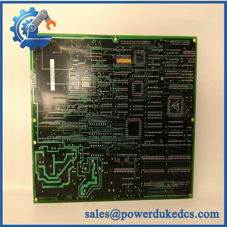
GE DS200IQXSG1AAA
Application Scenarios & Pain Points
Micro-case — repeated inverter trips appear immediately after a switching event. A snubber circuit is intended to manage switching transients, so a damaged snubber assembly can become relevant when abnormal voltage stress appears around the associated power stage. The inverter power circuit, semiconductor devices, and associated wiring must still be checked before the board is condemned.
Within GE EX2000 excitation equipment, the DS200IQXSG1AAA is listed as an inverter snubber board. The board sits in the power-electronics support layer rather than the control-logic layer, which means a failure may manifest through drive or excitation behavior instead of a conventional controller alarm.
For legacy Mark V drive cabinets, the eight E1–E8 terminals provide a useful physical identification point. Compare terminal labeling and connector arrangement before installing a spare, because other DS200 boards can have similar board dimensions while serving completely different functions.
At cabinets operating around 50°C, inspect the board for discoloration around capacitors, resistors, semiconductor devices, and connector solder joints. An exact environmental rating for this specific board was not verified, so the original GE drive cabinet specification should remain the governing engineering reference.
🚨 Common Error Codes & Diagnostic Symptoms
The DS200IQXSG1AAA is a passive protection PCB and does not have its own standard numerical firmware fault-code system. Diagnosis normally comes from the associated Mark V/EX2000 drive behavior, electrical measurements, visual inspection, and system-level alarms.
Symptom/Code: Repeated inverter overvoltage or switching-related trip → Diagnosis: Possible snubber-circuit degradation, damaged film capacitor, failed suppression component, loose terminal connection, or a separate inverter power-stage problem. → Action: Inspect the complete transient-suppression circuit and associated power stage; replace the snubber board after confirming the fault is localized to the board.
Symptom/Code: Visible discoloration or cracking around C5 or nearby components → Diagnosis: Possible electrical overstress, thermal damage, or component failure within the suppression network. The documented board includes a film capacitor and multiple passive/semiconductor components. → Action: Remove the board from service, inspect the associated inverter circuit, and replace the board when component damage is confirmed.
Symptom/Code: Intermittent drive instability after thermal cycling → Diagnosis: Possible marginal solder joints, degraded terminal connections, capacitor deterioration, or other board-level component changes. → Action: Inspect the board under controlled conditions and compare against a known-good assembly before replacing other inverter-control hardware.
🚨 Cross-Reference & Lifecycle Migration
Cross-Reference
The closest identity references for are within the same IQXS family. Current GE Mark V inventories list:
- DS200IQXSG1
- DS200IQXSG1A
The longer identifier carries the detailed revision information. These identifiers should be retained as search and identity references, but a shorter number should not automatically be treated as an engineering-approved substitution for the full A/A/A configuration.
Other inverter snubber cards such as DS200IQXDG1A and other DS200 snubber assemblies appear in the same Mark V family, but they are separate board identities. Do not substitute them solely because their descriptions contain “Inverter Snubber.”
Firmware Requirement
No firmware flashing is required for the itself.
The available technical description identifies a hardware protection circuit containing passive and discrete electronic components rather than a software-configured controller. Its function therefore depends on the electrical design and physical configuration of the board, not on downloadable application firmware.
Lifecycle Status
Status: Obsolete / Legacy
The Mark V product family is a legacy GE turbine-control platform, and current inventories primarily support existing installations through specialist service and replacement channels. The remains listed within the Mark V board family as an inverter snubber board.
For buffer stock, record the , application, physical board configuration, and condition. A generic “GE snubber board” inventory description is too broad for controlled replacement.
Field Engineer’s Tech Notes
Warning 1 — Do not judge the board by appearance alone.
A snubber network can look physically intact while its suppression components have degraded electrically. Inspect the film capacitor, resistive elements, semiconductor components, terminal connections, and solder joints with the power stage isolated.
Warning 2 — Photograph E1–E8 before removal.
The board has eight identified field terminals, and cable reconnection errors can create a completely different fault after maintenance. Record the cable position, terminal labels, connector orientation, and board mounting points before extraction (this takes minutes and can prevent an extended restart investigation).
Strict QA & Testing SOP
Step 1 — Exact identity check
Verify from the actual board marking. Record the IQXS designation and the complete A/A/A revision information.
Step 2 — Physical inspection
Inspect the PCB surface, four mounting holes, terminal strip, eight-pin connector, component bodies, and board edges for impact, cracking, corrosion, contamination, or unauthorized repair.
Step 3 — Terminal inspection
Check all E1 through E8 terminals for damaged hardware, oxidation, loose connections, thermal discoloration, and damaged solder joints.
Step 4 — Capacitor inspection
Inspect the documented film capacitor, including the C5 position, for cracking, bulging, discoloration, mechanical movement, or signs of dielectric damage. Do not classify C5 as a battery.
Step 5 — Component-level inspection
Check resistors, diodes, transistors, integrated circuits, and other suppression components for visual damage and abnormal electrical readings according to the approved GE test procedure.
Step 6 — Continuity and isolation checks
With the board completely de-energized and isolated, perform controlled continuity and insulation checks at approved test points. Do not create arbitrary test voltages at undocumented terminals.
Step 7 — Passive-network verification
Compare measured component values against the applicable schematic or known-good reference board. Particular attention should be given to the suppression path rather than simply checking that all terminals have continuity.
Step 8 — Controlled installation test
Install the board into an approved compatible Mark V/ test environment. Confirm correct physical seating, terminal orientation, and connector engagement.
Step 9 — Power-stage observation
Where the appropriate GE test fixture is available, operate the associated inverter or excitation system under controlled conditions while monitoring transient behavior and system diagnostics.
Step 10 — Thermal observation
Monitor the board and surrounding power electronics for abnormal heating, discoloration, or repeated trip behavior during an extended controlled test.
Step 11 — Documentation
Record part number, revision, terminal configuration, measured values, inspection results, photographs, test equipment, and QA disposition.
Step 12 — ESD-safe packaging
After testing, place the board in suitable ESD shielding material. Protect the terminal strip, eight-pin connector, film capacitor, and board corners from mechanical impact during shipment.
Test videos are available for applicable units tested in a compatible GE Mark V/ environment.
Buyer’s FAQ
Can I hot-swap the ?
Do not assume hot-swapping is permitted. This board belongs to the inverter power-electronics section of a legacy GE control system and can be connected to circuits carrying hazardous electrical energy. Follow the approved Mark V/ maintenance procedure and isolate the associated power stage before removal.
How do I verify a New Original ?
Request photographs of the actual PCB, including the complete part number, A/A/A revision markings, E1–E8 terminal labels, eight-pin connector, C5 film capacitor, board mounting holes, and overall condition. A generic image of an “IQXS” board does not establish the exact revision.
Is DS200IQXSG1A the same replacement as ?
The shorter DS200IQXSG1A identifier belongs to the same IQXS board family, while provides the extended revision identification. Current Mark V inventories also list DS200IQXSG1 and other IQXS variants. Treat the shorter identifiers as related search references unless the installed GE documentation confirms interchangeability.
What HS tariff code should be used?
The final HS/HTS classification depends on the importing country’s tariff schedule and the verified customs function of the board. Since this item is an inverter snubber/protection PCB, do not classify it automatically as a PLC CPU or general analog I/O card.
Have the destination-country customs broker confirm the complete national tariff classification before filing.
Does the include the latest firmware?
No. The board is identified as a hardware inverter snubber assembly and has no independently documented application firmware. Its electrical function comes from the installed suppression components and circuit topology.
What warranty should I expect?
Warranty depends on the supplier’s written commercial terms and the condition category of the board. For discontinued Mark V hardware, obtain the warranty period, functional-test scope, actual board photographs, revision information, and return conditions before purchase. A third-party warranty should not be represented as a GE factory warranty unless separately documented.











 Start Chat


