

Description
- Model: DS200SDCCG5AHD
- Brand: GE
- Series: Mark V Speedtronic
- Product Type: Drive Control Card / SDCC
- Mark V Grouping: Group 5
- Assembly Type: Normal DS200 assembly
- Functional Abbreviation: SDCC
- Primary Function: Main control circuitry for compatible drives or exciters
- Processor Architecture: Three 16-bit microprocessors with dual-ported RAM
- Processors: Drive Control Processor (DCP), Motor Control Processor (MCP), Co-motor Processor (CMP)
- Diagnostic Interface: 10 onboard diagnostic LEDs
- Memory Architecture: DS200 SDCC card uses sockets for application memory; the referenced GE manual states that the DS200 version does not include the five memory chips supplied on the DS215 version
- Factory Configuration: Jumper and wire-jumper settings are application dependent
- Documentation: GEI-100029C
- Approximate Board Weight: Commonly listed around 1.5 lb / 0.68 kg; packed shipment weight varies by packaging method
- Lifecycle Position: Legacy Mark V hardware
The DS200SDCCG5AHD is documented as a GE Mark V SDCC Drive Control Card with a Group 5 designation and three significant revisions. Current specialist listings identify the AHD suffix as two functional revisions plus one artwork revision.
Product Introduction
The GE DS200SDCCG5AHD Drive Control Card is a processor-based control PCB used in compatible GE Mark V drive and exciter architectures. The SDCC provides the primary control circuitry and interfaces required to process drive, motor, and customer I/O signals. GE documentation describes the SDCC architecture around three 16-bit processors connected through dual-ported RAM, allowing separate processing roles for drive control, motor control, and optional math-intensive co-motor functions.
This part number deserves exact-order verification because the SDCC family contains different functional groups and revisions. The G5 designation identifies the Group 5 version, while AHD identifies a particular revision combination. The same physical card family can contain different connector populations, jumper settings, memory arrangements, and application behavior. Treating the base number alone as sufficient for interchangeability can create a commissioning problem in a legacy drive cabinet.
Core Technical Specifications
| Specification | Details |
|---|---|
| Manufacturer | GE General Electric |
| Complete Part Number | DS200SDCCG5AHD |
| Product Type | Drive Control Card |
| Functional Abbreviation | SDCC |
| Product Family | Mark V / Speedtronic |
| Mark V Group | Group 5 |
| Assembly Type | Normal DS200 assembly |
| Revision Identifier | AHD |
| Revision Quantity | 3 significant revisions |
| Primary Function | Drive or exciter control |
| Processor Count | 3 |
| DCP | 80C186-class Drive Control Processor |
| MCP | 80C196-class Motor Control Processor |
| CMP | TMS320C25-class Co-motor Processor |
| Memory Interface | Dual-ported RAM architecture |
| Diagnostic LEDs | 10 |
| Diagnostic Code Range | Faults 1–1023 |
| Connector System | Multiple numbered PL connectors |
| Expansion Provisions | Supports compatible auxiliary boards |
| Configurable Hardware | JP jumpers and WJ wire jumpers |
| Reset Function | Onboard RESET pushbutton plus system/software reset paths |
| Testpoints | Multiple onboard electrical testpoints |
| Instruction Manual | GEI-100029C |
| Approx. Board Weight | About 1.5 lb / 0.68 kg |
| Lifecycle | Legacy Mark V platform |
The GEI-100029C documentation identifies the SDCC architecture as three 16-bit microprocessors coupled through dual-ported RAM. It also identifies the principal connector groups, including interfaces to power/interface boards, LAN communications, drive terminal boards, signal-processing boards, and meter outputs.
Memory and Replacement Note
One of the most important replacement distinctions is between DS200SDCC and DS215SDCC hardware. GE’s documentation states that the DS215SDCC contains five memory chips—four EPROMs and one EEPROM—while the DS200SDCC card does not include those five memory chips and the corresponding sockets are empty. A replacement strategy therefore should not assume that a DS215 and DS200 board have the same memory implementation.
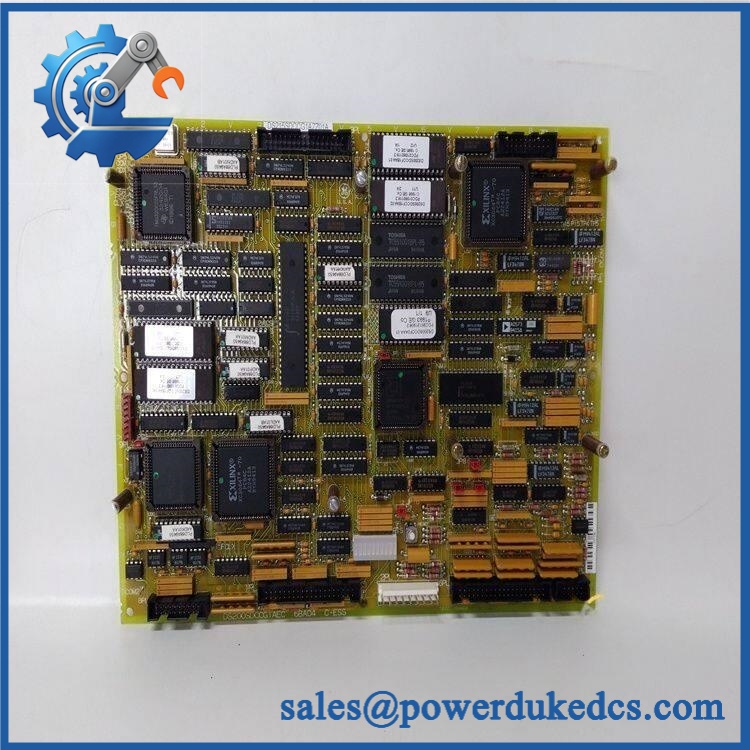
GE DS200SDCCG5AHD
Application Scenarios & Maintenance Considerations
Legacy Drive Control
The SDCC operates as the main processor board within compatible GE drive architectures. It processes control signals and communicates with other controller boards through the numbered PL connectors.
Maintenance priority: Verify the complete board number, group designation, revision markings, connector population, and application configuration before installation.
Exciter and Motor Control
GE documentation states that the SDCC provides control functions for drives and exciters. The DCP handles higher-level control functions, the MCP handles motor-control loops, and the CMP provides additional mathematical processing when the application requires it.
A replacement board should therefore be treated as a control-system component, not merely as a generic PCB.
Diagnostic and Commissioning Work
The board includes 10 diagnostic LEDs. GE documentation states that fault numbers from 1 through 399 are displayed using BCD coding, while fault numbers 400 through 1023 use binary coding. A no-fault or non-running condition produces a sequential LED pattern.
This makes the LED bank useful during first-level troubleshooting before deeper testing of external boards, wiring, software configuration, or drive power electronics.
Critical Spare Inventory
For a plant with an aging Mark V installation, a verified spare DS200SDCCG5AHD can reduce the recovery window following a processor-board failure. Inventory records should include the full part number, revision identifier, installed equipment, board configuration, and any documented memory-transfer requirements.
Obsolescence Risk
Mark V is a legacy GE control platform, so availability is increasingly dependent on specialist inventories, tested surplus, and repair capability. The DS200SDCC family has multiple group variants, and the DS215 replacement path described in GE documentation is not simply a case of treating the DS200 and DS215 boards as electrically identical.
For critical assets, carrying one validated spare with configuration documentation is generally easier to manage than sourcing an unknown revision after an outage has already started.
Common Diagnostic Symptoms
Symptom: SDCC Does Not Complete Normal Startup
Diagnosis: Check the onboard diagnostic LED sequence, control power inputs, processor-related conditions, memory configuration, and communications with the associated boards.
Action: Record the exact LED fault number before resetting the system. GE documentation notes that a hard reset trips the system and should not normally be performed while running.
Symptom: Unexpected Diagnostic Fault Code
Diagnosis: Identify whether the displayed code falls within the 1–399 BCD range or 400–1023 binary range.
Action: Decode the complete LED pattern first, then compare it against the applicable drive documentation. Do not replace the SDCC solely because an LED fault is present; the underlying problem may exist on another connected board or signal path.
Symptom: Drive Configuration Lost After Board Replacement
Diagnosis: Check the actual SDCC memory arrangement and compare the replacement type with the original board. GE specifically distinguishes the SDCC from the DS215SDCC regarding the five memory chips.
Action: Confirm whether the replacement card is the correct configuration before transferring or restoring application data.
Symptom: Incorrect Drive or I/O Response
Diagnosis: Review connector assignment and configurable hardware. The SDCC interfaces with multiple boards through numbered PL connectors, while jumpers and wire jumpers establish certain hardware options.
Action: Compare the replacement board against the original controller test data and applicable GE instructions before changing any jumper position.
Cross-Reference & Lifecycle Migration
The DS200SDCC family includes several functional groups. GE documentation identifies G1, G3, and G4 applications in its published SDCC documentation, while current specialist catalogs also identify a G5 grouping represented by the DS200SDCCG5A/G5AHD family. The G5 board should therefore be matched by its complete part number and installed-system documentation rather than by the SDCC base name alone.
vs. DS215
The DS215SDCC is documented as a replacement path for the DS200SDCC, but the two are not equivalent from a memory-content standpoint. GE states that the DS215 includes five onboard memory chips while the card does not include those chips.
Revision Control
For DS200SDCCG5AHD, the AHD suffix represents a specific revision combination. When sourcing a replacement, record:
- Complete part number
- Functional revision markings
- Artwork revision
- Mark V grouping
- Connector population
- Memory configuration
- Existing jumper positions
- Installed drive/exciter configuration
This information provides a much stronger compatibility check than matching only the “DS200SDCC” family name.
Firmware and Configuration
The SDCC supports software configuration through the applicable GE configuration tools. GE documentation identifies ST2000, GE Control System Toolbox, and the LynxOS Drive Configurator as configuration environments for applicable equipment.
Software or memory changes should therefore be treated as system-specific engineering work. Do not assume that a generic firmware package can be loaded to any SDCC revision.
Field Engineer’s Tech Notes
1. Do not press RESET on a running system as a routine diagnostic step.
GE documentation explicitly states that the system trips when a hard reset is initiated and that the system should not normally be reset while running.
2. Record the factory configuration before changing jumpers.
GE states that most jumper selections are factory set and that the controller test data sheets indicate the intended positions. Incorrect hardware configuration can affect board behavior and application compatibility.
Strict QA & Testing SOP
Part Number Verification
Confirm character by character. Check the GE identification marking, board ID, revision markings, and visible hardware configuration.
Physical Inspection
Inspect:
- PCB surface and solder joints
- Connector pins and headers
- EPROM/EEPROM socket areas
- Capacitors, resistors, diodes, and resistor networks
- Processor devices
- Diagnostic LED bank
- Reset button
- Daughterboard mounting provisions
- Mounting holes and board edges
Any oxidation, contamination, cracked solder joints, bent pins, or impact damage should be documented before acceptance.
Configuration Inspection
Record all visible JP and WJ settings before shipment. Compare them with the intended application documentation rather than relying on a generic default configuration.
Electrical Testing
Where a suitable Mark V drive test environment is available, functional testing should cover board power rails, processor startup behavior, diagnostic LED operation, connector-level I/O, and relevant communication paths.
The GE manual identifies onboard testpoints including regulated +5 V, ±15 V, timing signals, motor-current representation, oscillator signals, and other diagnostic points.
ESD Protection
The should be handled as an ESD-sensitive electronic assembly. Use an ESD-safe work area and protective packaging, with additional mechanical protection around connectors and exposed board edges during shipment.
QC Documentation
A professional spare-parts package can include:
- Part-number verification record
- Serial or identification record where available
- Visual inspection report
- Test report
- Configuration record
- Packing photos
- Test video upon request
Buyer’s FAQ
What is the GE ?
It is a GE Mark V SDCC Drive Control Card used for compatible drive and exciter control applications. The board contains three primary processor functions and interfaces with other control hardware through multiple PL connectors.
How many processors are on the SDCC?
The SDCC architecture uses three 16-bit microprocessors: a Drive Control Processor, Motor Control Processor, and Co-motor Processor. The CMP is used when the application requires its additional processing capability.
Does the contain the same memory arrangement as a DS215SDCC?
No. GE documentation states that the DS215SDCC contains five memory chips, consisting of four EPROMs and one EEPROM, while the does not include those five chips. This distinction should be checked before any replacement or memory-transfer activity.
How does the SDCC display faults?
The board has 10 diagnostic LEDs. Faults numbered 1–399 use BCD coding, while faults 400–1023 use binary coding.
Does have configurable hardware?
Yes. The SDCC family includes manually adjustable JP jumpers and wire jumpers. GE notes that most selections are factory configured and should be checked against the controller’s test data before modification.
What manual should be referenced?
The applicable GE documentation is GEI-100029C, titled Drive Control Card. The document covers functional description, connector assignments, testpoints, configurable hardware, software configuration, replacement procedures, and memory handling.
What should be confirmed before purchasing a replacement?
Provide the complete part number together with the existing board revision, installed equipment type, connector configuration, memory arrangement, and available controller documentation. For legacy Mark V equipment, these details are important because different SDCC groups and revisions are not automatically interchangeable.











 Start Chat


