

Description
- Model: GE DS200SDCIG2AEB
- Brand: GE / General Electric
- Series: Mark V DS200 / DC2000
- Part Type: SDCI DC Power Supply and Instrumentation Board
- Functional Acronym: SDCI
- Core Function: Supplies regulated control power and provides instrumentation/interface circuits for compatible DC2000 drives.
- Key Configuration: G2 identifies the external-exciter version; the full AEB suffix records two functional revisions and one artwork revision.
- Primary Manual: GEI-100173 — SDCI DC Power Supply and Instrumentation Board replacement procedure.
Product Introduction
A DC2000 drive can lose several seemingly unrelated functions when its internal control-power source becomes unstable. The GE DS200SDCIG2AEB sits directly in that part of the architecture: it is the SDCI DC Power Supply and Instrumentation Board, providing logic-power rails and interface circuitry for DC2000 drives with input voltages up to 600 VAC. The G2 designation identifies the version used with external exciters.;
This board should be treated as a high-risk maintenance component during handling. It is static-sensitive, contains stored-energy capacitors, and incorporates adjustable hardware features including JP1, JP2, and SW1. GE’s applicable replacement manual is GEI-100173, and specialist documentation identifies the exact unit as normal coating, functional revision A/E, artwork revision B.
Core Technical Specifications
| Parameter | Value |
|---|---|
| Manufacturer | GE / General Electric |
| Catalog Number | DS200SDCIG2AEB |
| Product Family | Mark V DS200 / DC2000 |
| Functional Acronym | SDCI |
| Hardware Type | DC Power Supply and Instrumentation Board |
| Exciter Configuration | G2 — External Exciter |
| Parent Board | DS200SDCIG2A |
| Functional Revision 1 | A |
| Functional Revision 2 | E |
| Artwork Revision | B |
| PCB Coating | Normal Coating |
| Applicable Manual | GEI-100173 |
| Drive Interface | DC2000 |
| Supported Drive Input | Up to 600 VAC |
| DC Power Supply 1 | +5 VDC, 4 A |
| DC Power Supply 2 | ±15 VDC, 0.4 A |
| DC Power Supply 3 | ±24 VDC |
| AC Supply Circuit | 115 VAC, 0.4 A |
| Instrumentation Functions | Motor-field, driver, AC-line, and DC-motor signal interface circuits |
| Hardware Adjustments | JP1, JP2, SW1 |
| Fuse Count | Up to 6 documented on the SDCI family |
| Static Sensitivity | Yes |
| Reported Unit Weight | Approx. 1 lb / 0.45 kg |
| Reported Dimensions | Approx. 120 × 100 × 30 mm in one secondary record |
| Estimated Shipping Weight | Approx. 0.8–1.3 kg with ESD and impact packaging |
| Operating Temperature | Exact OEM limit for this revision not independently verified |
| Storage Temperature | Exact OEM limit for this revision not independently verified |
| Heat Dissipation | Exact board-level OEM figure not independently verified |
| Standalone Firmware | None documented |
| Lifecycle | Legacy / Obsolete |
The power-rail and functional descriptions above are based on the SDCI family documentation and exact-part records. The SDCI provides +5 VDC at 4 A, ±15 VDC at 0.4 A, ±24 VDC, and a 115 VAC, 0.4 A supply circuit, along with motor-field, driver, and instrumentation interfaces.;
The exact-part record gives a weight of 1 lb. The 120 × 100 × 30 mm dimension comes from a lower-confidence secondary listing and should be treated as a shipping-planning reference only; measure the actual board before formal freight quotation.;
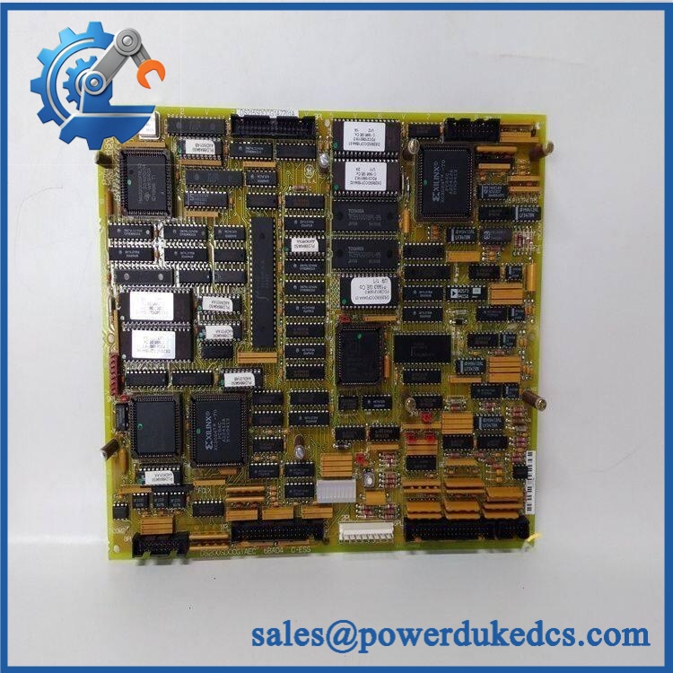
GE DS200SDCIG2AEB
Application Scenarios & Pain Points
Micro-case — drive logic dropout: A drive repeatedly loses control power while the incoming plant supply remains stable. The SDCI board becomes a logical diagnostic target because it generates several internal control-power rails and carries instrumentation circuitry.
For legacy turbine-drive cabinets, the G2 version is specifically associated with external exciters. That distinction matters when comparing the board against G1A-family SDCI assemblies. A similar-looking PCB from the wrong exciter architecture should not be treated as electrically interchangeable.
In industrial motor-drive applications, the board supports motor-field and driver circuits in addition to low-voltage control rails. A fault on one section can therefore present as a drive-control problem rather than an obvious power-supply failure.
For maintenance teams working on aging Mark V cabinets, the onboard fusing provides a useful diagnostic point. The SDCI family documentation identifies multiple fuses, including a fuse dedicated to low-level negative supply circuits. A blown fuse should be investigated as evidence of an underlying fault, not simply replaced repeatedly.
At 50°C+ cabinet temperatures, thermal inspection should include the transformers, semiconductors, fuse area, electrolytic capacitors, and solder joints. The exact continuous temperature specification for this AEB revision was not independently verified, so the original /Mark V cabinet specification should control.
🚨 Common Error Codes & Diagnostic Symptoms
No authoritative GE document located for DS200SDCIG2AEB defines a universal numerical fault-code set for the PCB itself. The following are board-level diagnostic symptoms.
Symptom/Code: Internal control power missing or unstable → Diagnosis: A failed fuse, regulator section, transformer, semiconductor, or PCB fault may interrupt one or more generated supply rails → Action: Verify the external supply and fuse chain first, then measure the applicable control rails and replace the SDCI when the board is confirmed defective.
Symptom/Code: Drive trips or control drops out after an apparent normal startup → Diagnosis: A marginal power rail or instrumentation circuit can fail under operating load even when static voltage checks look acceptable → Action: Monitor the relevant rails under representative conditions and replace the board when the fault follows it.
Symptom/Code: Fuse repeatedly opens after replacement → Diagnosis: Possible downstream short, failed power component, damaged MOV/protection device, or overload condition → Action: Do not increase the fuse rating; locate the fault and replace the SDCI only after the external circuit has been cleared.
🚨 Cross-Reference & Lifecycle Migration
Exact Identity
GE DS200SDCIG2AEB = SDCI DC Power Supply and Instrumentation Board, Mark V DS200, G2 external-exciter configuration. The exact-part record identifies functional revision A, second functional revision E, and artwork revision B.
The underlying parent board is DS200SDCIG2A. Related suffixes include DS200SDCIG2ABA, DS200SDCIG2ADA, DS200SDCIG2AFB, DS200SDCIG2AGB, and DS200SDCIG2AHB. These should be treated as related revisions, not automatic replacements, until the applicable GE documentation confirms compatibility.
Revision and Configuration Control
The G2 identifier is significant because the SDCI family uses different groupings for exciter architecture. Secondary documentation identifies G2 assemblies as being used with external exciters.
The JP1 control-source jumper, JP2 MA contactor drop-out-time jumper, and SW1 AC-line selection switch should be documented before removal. GE’s replacement guidance specifically covers these hardware adjustments.
Firmware Requirement
No standalone user firmware applies to the SDCI board. It is a power-supply and instrumentation PCB, not a programmable Mark V processor.
Replacement compatibility is therefore governed by the drive model, exciter arrangement, PCB revision, jumper configuration, fuse arrangement, connectors, and applicable system wiring rather than by firmware flashing.
Lifecycle Status
Lifecycle: Legacy / Obsolete.
GE Vernova currently states that Mark V is no longer produced and new parts are not available. GE reports limited refurbished parts, repair and exchange options, and identifies full replacement with Mark VIe as the modern control-system migration route.
For a plant still operating /Mark V equipment, this favors controlled spare stocking and documented migration planning. Retain exact board revisions and configuration data with every critical spare.
Field Engineer’s Tech Notes
First warning: discharge stored energy before touching the board. The SDCI contains capacitors that can retain hazardous voltage after external power is removed. Verify the board is electrically safe with appropriate test equipment rather than relying on elapsed time alone.
Second warning: copy JP1, JP2, and SW1 exactly before removal. These are adjustable hardware features documented for the SDCI family. An otherwise healthy replacement can behave incorrectly when the original configuration is not reproduced.
Also treat the PCB as ESD-sensitive. Hold it by the edges, use a grounded wrist strap, and place it only on approved static-protective material.
Strict QA & Testing SOP
1. Inbound identity verification
Confirm DS200SDCIG2AEB, SDCI designation, G2 configuration, and A/E/B revision data. Photograph the complete board before unpacking further.
2. Physical inspection
Inspect the PCB for cracked solder joints, corrosion, overheated components, damaged terminal areas, broken connectors, capacitor leakage, and signs of previous repair.
3. Fuse inventory
Verify all fitted fuse positions and ratings against the applicable GEI-100173 documentation. Do not assume every DS200SDCIG2A variant uses an identical fuse arrangement.
4. Jumper and switch documentation
Record JP1, JP2, and SW1 positions. Compare them with the removed board or approved drive documentation.
5. Pre-power electrical inspection
Check relevant resistance and continuity paths before energizing. Pay particular attention to suspected shorted power components and stored-charge conditions.
6. Controlled power-up
Use an isolated, current-limited test source appropriate to the verified application. Monitor input current and fuse behavior.
7. Power-rail verification
Measure the documented SDCI supply outputs, including +5 VDC, ±15 VDC, ±24 VDC, and 115 VAC where applicable, using the exact acceptance values from the applicable service documentation.
8. Instrumentation-function testing
Check the applicable motor-field, driver, AC-line, and DC-motor signal circuits using the approved test procedure.
9. Load testing
Operate the board with representative controlled loads while monitoring supply stability, fuse behavior, component temperature, and abnormal noise.
10. Exciter compatibility test
Verify the board is being tested in a G2 external-exciter application and that the host drive configuration matches the board.
11. Extended observation
Monitor the power rails and interface circuits for drift, intermittent dropouts, abnormal thermal rise, and repeated protection action.
12. Final preservation
Place the approved board in ESD shielding packaging, protect connectors and adjustment hardware, and attach the QC record.
Test videos are available when live-rig testing is performed and visual evidence is required for procurement approval.
Buyer’s FAQ
Is a generic DC power-supply board?
No. It is a Mark V SDCI DC Power Supply and Instrumentation Board used as an interface to . It also contains instrumentation and drive-interface circuits, so a generic industrial power supply is not an equivalent replacement.
Can I replace AEB with another DS200SDCIG2A revision?
Not automatically. The SDCI family contains multiple G2 revisions, including ABA, ADA, AFB, AEB, AGB, and AHB variants. Confirm the complete suffix, jumper settings, fuse arrangement, exciter architecture, and host-drive documentation before substitution.
Can the board be hot-swapped?
No routine hot-swapping should be assumed. The board contains hazardous-energy circuits and capacitors that can remain charged after power removal. GE’s replacement procedure should be followed with the drive fully isolated and discharged before board removal.
How do I verify New Original authenticity and warranty?
Request photographs of the actual , including the GE identification label, SDCI/G2 designation, A/E/B revision markings, fuse area, jumpers, switch, connectors, and factory packaging. The purchase record should clearly state New Original, New Surplus, refurbished, or repaired condition, together with the functional-test scope and warranty duration.
For controlled inventory, also record the exact GE part number, revision, exciter type, jumper/switch settings, fuse configuration, COO, QC result, and packaging condition. GE currently states that Mark V is no longer produced and that new parts are unavailable, making exact legacy-spare traceability particularly important.











 Start Chat


