
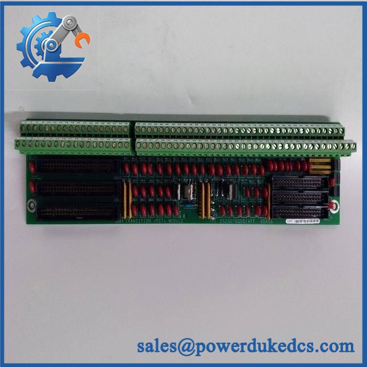

Description
- Model & Brand: GE General Electric DS200TBQCG1AAA
- Series: Mark V Turbine Control System
- Part Type: RST Analog Input Milliamp I/O Termination Board
- Functional Acronym: TBQC
- Physical Dimensions: Approx. 11.25 × 3.00 in / 286 × 76 mm, board envelope
- Estimated Shipping Weight: Approx. 0.7–1.0 kg packed; verify actual packed weight before freight booking
- Terminal Blocks: 2
- Terminal Capacity: 83 terminals per block; 166 signal-wire termination positions total
- Jumpers: 15
- Board Connectors: 3 × 40-pin and 3 × 34-pin connectors
- Document Reference: GEH-6153
- Board Mounting: Four corner mounting holes
- What’s in the Box: DS200TBQCG1AAA board and ESD protective packaging; terminal hardware, cables, mounting screws, and original documentation only when specifically listed on the PO
- Handling Class: ESD-sensitive PCB; protect terminal blocks, connector headers, jumper assemblies, and exposed circuitry
The board is identified as a GE Mark V TBQC analog termination board. Its two 83-position terminal blocks and multiple control-system connectors provide the physical interface for analog and position-related signals within the Mark V architecture.
Product Introduction
Architecture Hook
The DS200TBQCG1AAA mounts inside the GE Mark V control-system cabinet and serves as an analog signal termination interface rather than as a standalone CPU or I/O processor. The board is associated with the RST analog termination function and is commonly installed at the designated TBQC position, where it interfaces with other Mark V boards through its high-density connectors.
For physical asset management, the complete board identity matters. Two 83-terminal blocks provide 166 possible signal termination positions, while 15 jumpers permit application-specific hardware configuration. GE documentation references the board under instruction manual GEH-6153, and replacement work should preserve the original jumper state and terminal wiring record (especially on turbine systems where undocumented changes can create difficult commissioning faults).
Core Technical Specifications
| Parameter | Value |
|---|---|
| Manufacturer | GE General Electric |
| Part Number | DS200TBQCG1AAA |
| System | Mark V Turbine Control |
| Functional Name | Analog Input Milliamp I/O Termination Module |
| Board Type | RST Analog Termination Board |
| Functional Acronym | TBQC |
| Terminal Blocks | 2 |
| Terminals per Block | 83 |
| Total Signal Terminations | 166 |
| Jumpers | 15 |
| 40-Pin Connectors | 3 |
| 34-Pin Connectors | 3 |
| Document Reference | GEH-6153 |
| Mounting | Four corner mounting holes |
| Board Length | Approx. 11.25 in / 286 mm |
| Board Height | Approx. 3 in / 76 mm |
| Power Role | Signal termination/interface; not a standalone power supply |
| Firmware | No standalone firmware function |
| Lifecycle | Legacy / Obsolete Mark V hardware |
The electrical role and connector count are supported by independent Mark V technical references. The physical dimensions are also consistently reported as approximately 11.25 inches long by 3 inches high.
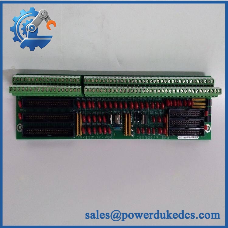
GE DS200TBQCG1AAA
🚨 Global Compliance & Industry Certifications
- CE Mark: Do not assume a standalone CE approval from the DS200TBQCG1AAA part number. Certification may apply to the complete Mark V equipment configuration rather than the individual PCB.
- UL / cUL: No standalone UL or cUL certificate was verified for this exact board from the technical references reviewed. Do not enter a UL claim into the compliance record without documentary evidence.
- ATEX / IECEx: No standalone ATEX or IECEx certification was verified for DS200TBQCG1AAA. The bare PCB should not be treated as hazardous-area equipment merely because the turbine system may operate in a classified facility.
- Marine Approvals: No exact DNV, ABS, or other marine certificate was verified for this board. Marine acceptance must be established for the complete control-system installation.
- System EMC Compliance: Where the Mark V installation has certification documentation, retain the system-level EMC/conformity records with the cabinet asset file.
For Class I, Division 2 or other hazardous-location applications, the certification applies to the approved equipment configuration, enclosure, wiring, and installation method—not simply to the replacement PCB.
Verify specific lot certifications with OEM.
🚨 Long-Term Storage & Asset Preservation Guide
Keep the inside an ESD shielding bag. The board has exposed terminal hardware, jumper assemblies, and multiple high-density connector interfaces. Bare-board storage invites oxidation, contamination, and electrostatic damage.
Maintain warehouse humidity below 60% RH where practical. The board itself is not an environmental enclosure; moisture exposure can attack connector contacts and soldered terminations long before obvious corrosion becomes visible. Use desiccant for sealed long-term storage and avoid temperature cycling that produces condensation.
Preserve the jumper configuration with the serialized asset. Photograph every jumper position before the board enters storage. GE Mark V replacement guidance specifically emphasizes transferring jumper positions from the defective board to the replacement board, because the installed configuration may differ from factory defaults.
Protect terminal-block threads and connector pins. Do not stack boards with the terminal blocks facing each other. Use rigid separators or the original packaging so mechanical pressure cannot deform the terminal hardware.
Physical Installation Prerequisites
Install only in the intended GE Mark V TBQC/RST termination architecture. This is a mechanically mounted PCB, not a universal plug-in I/O module.
The documented board envelope is approximately 286 mm × 76 mm, with a mounting hole near each corner. Verify the actual rack plate and mounting-hole pattern before cabinet work; do not rely solely on a supplier’s dimensional listing.
No verified manufacturer-specific 50 mm clearance requirement was found for the board itself. Preserve the Mark V cabinet’s established ventilation, cable-routing, and service-access envelope instead. Space is also required for the two large terminal blocks and the mating high-density connectors.
Grounding should follow the complete Mark V cabinet design. Keep analog signal conductors separated from high-energy power and switching conductors where the original design permits.
Critical installation step: label every field wire by terminal-block identifier and terminal number before removal. The board has 166 termination positions, so one undocumented wire can become a lengthy troubleshooting exercise after reassembly.
Before energizing the turbine-control cabinet, compare all 15 jumper positions against the removed board and the approved Mark V drawing. Do not assume factory-default jumper placement is correct for the customer’s application.
Buyer’s FAQ — Logistics & Compliance Focus
Q1. What HS tariff code should be used for GE ?
Do not treat a supplier-provided tariff number as universally valid. One current supplier listing reports 8538900000, but the final classification depends on the importing country’s tariff schedule and customs interpretation of a dedicated turbine-control termination board. Use a precise customs description such as “GE Mark V analog I/O termination board, ” and have the broker validate the destination-country HS code.
Q2. Does the GE name establish the Country of Origin?
No. Brand and COO are separate trade-compliance facts. One current supplier record reports USA as the country of origin, but that should not automatically be applied to every historical unit or revision. Obtain a shipment-specific COO declaration and retain it with the commercial invoice.
Q3. Should I insure this board even though it is only a few hundred millimeters long?
For an obsolete Mark V board, insurance should be based on replacement exposure, not physical size. The board is compact, but a failed termination assembly can require extensive cabinet troubleshooting if an exact spare is unavailable. Record the serial number, jumper configuration, condition, declared value, package dimensions, and pre-shipment photographs.
Q4. Does a New Original include the latest firmware pre-loaded?
Firmware is not applicable to the board as a standalone programmable controller. The important configuration data is hardware-based, particularly the jumper settings and terminal wiring. GE-oriented replacement guidance specifically recommends matching jumper positions between the failed and replacement boards.
Q5. What should procurement retain for audit and receiving inspection?
Keep the exact part number, serial number, revision information, COO evidence, commercial invoice, packing list, certification documents where applicable, and receiving photographs. For this particular board, add the terminal wiring record and 15-jumper configuration to the asset file. That information can be more operationally valuable than the cosmetic condition grade when the spare is finally deployed.











 Start Chat


