

Description
- Model: DS200TCCBG1BED
- Brand: GE General Electric
- Series: Mark V Speedtronic / TC2000
- Part Type: Common Extended Analog I/O Board
- Functional Acronym: TCCB
- Functional Revision: B / E
- Artwork Revision: D
- Processor: Intel 80196 microprocessor
- Memory: Multiple socketed PROM modules
- Primary Interface: Mark V control-core and terminal-board signal architecture
- Connectors: 2 × 50-pin connectors JCC/JDD; additional 34-pin interfaces associated with the board assembly
- LED: 1 side-visible board LED
- Hardware Jumpers: J1–J5 for generator/bus-voltage and line-current monitoring; J14 for RS232/DCOM routing; J15/J16 for testing
- Primary Signal Types: 4–20 mA, 0–1 mA, RTD, PT/CT, generator voltage, bus voltage, line current
- Power: +5 VDC supplied through the Mark V power/interface architecture
- Approx. Shipping Weight: Secondary records range around 0.46–0.62 kg; weigh the actual packed unit for freight calculation
- Physical Dimensions: Secondary records vary; approximately 21 × 15 × 3.5 cm is reported for one inventory configuration. Verify the actual board before export packing.
- What’s in the Box: DS200TCCBG1BED PCB only unless the PO specifically includes PROM devices, cables, mounting hardware, or documentation
- Packaging: ESD shielding bag, rigid PCB support, connector protection, moisture-controlled outer carton
The DS200TCCBG1BED is identified as a Common Extended Analog I/O Board for the GE Mark V system. Its documented interfaces include JHH for 4–20 mA/0–1 mA inputs, JII for RTDs, JMP for PT/CT signals, 2PL for power, and 3PL for the internal data bus.
Product Introduction
Structure C — Compliance Hook
Using the exact DS200TCCBG1BED revision matters in a Mark V control cabinet because this board participates in turbine monitoring and signal-conditioning functions that cannot be validated by appearance alone. The TCCB processes additional analog information from terminal boards and other core boards, including 4–20 mA and 0–1 mA inputs, RTDs, generator and bus voltage signals, and line-current measurements. GE-associated service documentation identifies GEH-6153 as a relevant technical reference.
For lifecycle control, treat the board as a legacy Mark V asset and preserve its configuration history. The board contains an 80196 processor and multiple PROM modules, while five hardware jumpers provide application-specific monitoring selections. A like-for-like spare can avoid field rewiring and extensive turbine-control revalidation, but the replacement still needs matching PROM identification, jumper positions, connector assignments, and installed application. Secondary technical records specifically distinguish firmware and PROM handling from the physical PCB itself.
Core Technical Specifications
| Parameter | Value |
|---|---|
| Manufacturer | GE General Electric |
| Part Number | DS200TCCBG1BED |
| Series | Mark V Speedtronic |
| Board Acronym | TCCB |
| Product Type | Common Extended Analog I/O Board |
| Application | Mark V / TC2000 turbine control |
| Functional Revision | B / E |
| Artwork Revision | D |
| Processor | Intel 80196 |
| Memory | Multiple PROM modules |
| Primary Supply | +5 VDC through Mark V power architecture |
| Analog Inputs | 4–20 mA / 0–1 mA |
| RTD Interface | Yes |
| Generator Voltage Monitoring | Supported through jumper-configured circuits |
| Bus Voltage Monitoring | Supported |
| Line Current Monitoring | Supported |
| PT/CT Interface | Via JMP from TCEB |
| Core Data Bus | 3PL |
| Power Interface | 2PL from TCPS |
| Input Connector | JHH |
| RTD Connector | JII |
| PT/CT Connector | JMP |
| Additional Connectors | JKK, JTEST, TCQPL typically unused |
| Board LED | 1 side-visible LED |
| Hardware Jumpers | J1–J5, J14, J15, J16 |
| Firmware Architecture | PROM-based |
| Standalone Power Draw | Not reliably established in accessible documentation |
| Heat Dissipation | Load and cabinet dependent |
| Approx. Weight | 0.46–0.62 kg, secondary records |
| Approx. Dimensions | Around 21 × 15 × 3.5 cm, secondary record |
| Manual Reference | GEH-6153 |
| Lifecycle | Legacy / obsolete Mark V hardware |
The technical record identifies the board’s 80196 processor, PROM modules, JHH/JII/JMP interfaces, 2PL power input, and 3PL internal data bus. Secondary listings disagree on exact dimensions and weight, so those values should remain provisional until the actual asset is measured.
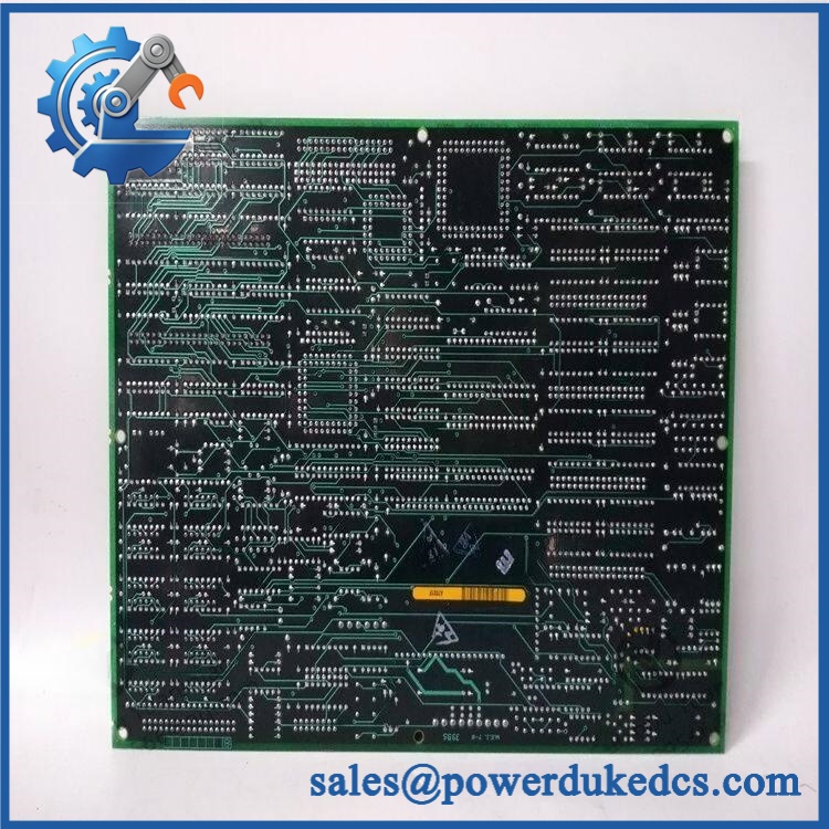
GE DS200TCCBG1BED
🚨 Global Compliance & Industry Certifications
- CE Mark: Do not make a standalone CE claim for the PCB without revision-specific supporting documentation. The board forms part of the complete Mark V equipment installation.
- UL/cUL: No reliable revision-specific evidence was established for a universal UL/cUL listing covering every DS200TCCBG1BED unit.
- ATEX/IECEx: Do not assume hazardous-area certification. The Mark V control cabinet may interface with classified-area field equipment, but that does not make the PCB independently certified for hazardous-area installation.
- Marine Approvals: No revision-specific DNV approval was established for this exact board from the available technical record.
- Electrical Safety: The board is integrated into a turbine-control cabinet with energized internal power circuits. Maintenance must follow the complete cabinet isolation procedure.
- Functional Safety: Do not assign a SIL rating directly to the TCCB PCB. Any safety claim belongs to the engineered turbine-control/protection function and its complete architecture.
- Documentation Traceability: Keep the complete part number, PCB revision, PROM identification, serial/date code, applicable technical manual, COO, and inspection report together.
Verify specific lot certifications with OEM.
🚨 Long-Term Storage & Asset Preservation Guide
Preserve the PROM configuration. The relies on socketed PROM modules for firmware/application instructions. Do not remove or exchange PROM devices during routine warehouse inspection; record their identification and location photographically instead. ([turn485530search1]turn485530search3)
Keep the PCB inside an ESD shielding bag. The board contains processor electronics, memory sockets, connectors, and hardware jumpers. Ordinary polyethylene wrapping without ESD shielding is not suitable for long-term controlled storage.
Control humidity and condensation. Maintain a clean, dry warehouse environment, preferably below 60% RH where the OEM storage specification is unavailable. Use desiccant in sealed packaging and inspect JCC/JDD connectors, PROM sockets, soldered components, and jumper hardware for oxidation during periodic asset audits.
Do not casually power-cycle a shelf spare. Record the PROM identifiers, jumper positions, board revision, serial/date code, packaging status, and last test date so the asset can be deployed without configuration reconstruction during a turbine outage.
Physical Installation Prerequisites
- Power Isolation: De-energize the complete Mark V cabinet and all applicable control/auxiliary supplies before removing the board.
- Board Position: Confirm the exact Mark V core slot and installed application from the site drawing.
- 2PL Connection: Verify the power connection from the TCPS architecture before insertion. ([turn485530search0]turn485530search4)
- 3PL Connection: Confirm the internal data-bus connection between the TCCB, TCCA, and STCA architecture.
- JHH: Verify the 4–20 mA / 0–1 mA input path from the associated TBCB terminal board.
- JII: Confirm RTD wiring and channel identification.
- JMP: Verify PT/CT wiring from the TCEB board.
- Jumper Settings: Photograph J1–J5, J14, J15, and J16 before removing the existing board. Reproduce the approved configuration exactly.
- PROM Devices: Compare PROM identifiers against the original board/application record before energization.
- Cooling: Keep cabinet airflow clear; do not bundle ribbon cables against heat-producing components.
- Grounding: Verify cabinet protective-earth continuity before restoring power.
- ESD: Handle the PCB only with grounded ESD controls.
- Service Access: Maintain enough front and rear access to safely reconnect all ribbon and interface cables without stressing the connectors.
The documented interface structure makes connector identification particularly important: 2PL provides power, 3PL carries the internal data bus, JHH carries mA inputs, JII handles RTDs, and JMP handles PT/CT signals.
Buyer’s FAQ
Q1. What HS tariff code should be used for GE ?
Do not classify the board from the generic phrase “analog module” alone. The is a dedicated turbine-control PCB used for analog signal conditioning and monitoring within the Mark V architecture. A classification review may consider headings for electrical control apparatus or parts thereof, but the final national tariff code must be determined from the importing country’s rules.
For the commercial invoice, use a precise description such as “GE Mark V Common Extended Analog I/O Board, turbine-control PCB” and have the importer or customs broker confirm the final HS classification.
Q2. What Country of Origin should appear on the COO?
Use the actual manufacturing origin supported by the physical board and supplier traceability. Current secondary records commonly identify USA as the origin, but that should not be copied automatically to every historical unit.
For audit purposes, retain the actual-unit photograph, serial/date code, supplier COO statement, and commercial invoice together.
Q3. Should I insure shipment of ?
For legacy Mark V turbine-control inventory, yes, insurance is sensible when the replacement is difficult to source. Protect the PROM sockets, connectors, card edge, and jumper field against mechanical impact and static discharge.
Photograph the complete PCB, revision markings, PROM devices, jumper positions, and packaging before dispatch. These records support both freight claims and receiving inspection.
Q4. Does include the latest firmware pre-loaded?
Do not assume it does. The board uses multiple PROM modules, and application behavior depends on the installed PROM/configuration set. The replacement should therefore be compared with the existing board’s PROM identification and jumper configuration before commissioning.
Q5. Can I replace any DS200TCCB board with ?
No. The TCCB family contains multiple hardware revisions and application variants. should be matched by complete part number, functional/artwork revision, connector arrangement, PROM configuration, jumper positions, and the associated Mark V terminal/core architecture. Secondary records specifically identify as the B/E functional revision with D artwork revision, so a shortened “TCB” description is insufficient for controlled procurement











 Start Chat


