

Description
- Brand: GE General Electric
- Full Model Number: EVMECNTM13
- Lifecycle Status: Legacy / application-specific excitation hardware
- Core Function: EXTB exciter terminal board for GE EX2100 excitation systems
- Top 3 Technical Specs: EXTB series; G2 model designation; simplex control / contactor-mode application
- System Compatibility: GE EX2100 excitation architecture
- Associated Hardware: EDEX board in documented excitation/de-excitation applications
- Board Type: Exciter terminal / I/O interface assembly
- Standalone Firmware: Not verified as a firmware-bearing controller
- Stock & Condition: New surplus / tested replacement subject to lot confirmation
- Shipping: Emergency dispatch subject to physical-stock verification and carrier cutoff
The most consistent technical identification for GE EVMECNTM13 is an EXTB exciter terminal board associated with the EX2100 excitation system. One technical listing identifies it as the second EXTB model, EXTB G2, with simplex control and contactor-mode use, while also describing its relationship with EDEX hardware.
Several current online listings incorrectly describe EVMECNTM13 as a modern motion-control or general-purpose industrial I/O module and attach unrelated processor, Ethernet, SERCOS, and firmware specifications to it. Those claims conflict with the EXTB identification and should not be used as purchasing specifications.
Obsolescence & Supply Chain Deep Dive
For plants operating a GE EX2100 excitation installation, failure of an EXTB terminal board can stop an otherwise serviceable excitation channel from operating correctly. Because EVMECNTM13 is an older, application-specific assembly, sourcing is generally driven by remaining inventory rather than normal production availability. The exact role matters: available technical references identify EVMECNTM13 as an EXTB G2 exciter terminal board, associated with simplex control and contactor-mode applications. It is also described as working with other EX2100 boards and, in specific applications, with an EDEX board.
The TCO case is therefore centered on preserving the installed excitation architecture. Replacing the terminal-board assembly can avoid a much larger engineering exercise involving cabinet redesign, field rewiring, control-system changes, and commissioning. A verified surplus spare may also reduce procurement lead time compared with searching for factory-new legacy inventory — although actual dispatch depends on physical stock, inspection status, export documentation, and destination. For a critical generator excitation system, record the exact EVMECNTM13 identifier and the existing EX2100 configuration in the asset register before approving a substitute.
Compatibility & Replacement Matrix
| Procurement / Engineering Item | Assessment |
|---|---|
| Replacement Classification | Conditional Drop-in Replacement |
| Primary System | GE excitation system |
| Board Family | EXTB exciter terminal board |
| Model Designation | G2 |
| Control Architecture | Simplex |
| Typical Operating Mode | Contactor mode |
| Firmware Flash Required | Not normally expected for the terminal-board assembly |
| Software Compatibility | Primarily determined by the surrounding hardware and application configuration |
| Hardware Modification | Normally none for an exact application match |
| EDEX Relationship | Verify where the installed application uses EDEX hardware |
| Typical Replacement Time | Approximately 2–4 labor hours, excluding fault isolation and commissioning |
| Budgetary Field Labor | Approximately USD 300–1,000 depending on site rates and outage procedures |
| Commissioning Requirement | Excitation-path verification, terminal checks, system diagnostics, and controlled functional testing |
Field Traps
Incorrect product-family identification:
is frequently mislabeled online as a general-purpose PLC I/O module, motion controller, or Ethernet communication device. Those descriptions include mutually inconsistent specifications such as ARM processors, SERCOS, EtherNet/IP, Modbus TCP, and 5 VDC power. They should not be accepted without OEM documentation. The EXTB / identification is the more consistent reference across the available technical material.
Simplex versus other configurations:
The available reference specifically identifies the EXTB G2 as a simplex control model used in contactor-mode applications. Do not assume that another EXTB variant can replace it merely because the board is physically similar. Verify the installed excitation topology first.
EDEX interface dependency:
Where the application uses an EDEX board for excitation de-excitation functions, the replacement must be evaluated as part of the complete excitation circuit. Do not approve the board based solely on the terminal-board number.
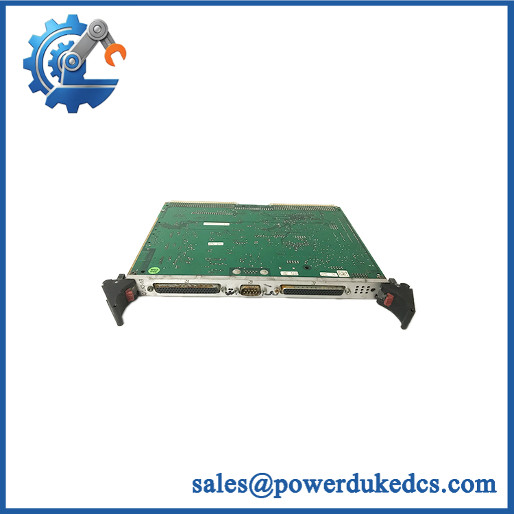
GE EVMECNTM13
Quality Assurance & Testing SOP
A surplus should undergo a configuration-specific inspection rather than a generic PLC module test.
OEM anti-counterfeit visual inspection
Verify the complete GE identification, marking, PCB or assembly labels, connector geometry, component population, terminal identification, mounting features, and manufacturing consistency. Photograph the identification area and both accessible sides.
Application and revision verification
Record every visible assembly or revision marking. Compare the supplied unit with photographs or records from the customer’s installed terminal board.
Power-on self-test
Install the board only in an approved test environment. Apply the system-specified control power through the correct test arrangement and observe the excitation-system startup sequence. Record all host-system diagnostic indications. Do not invent generic PLC-style RUN/ERR behavior for this board if such indicators are not documented on the actual assembly.
Terminal and I/O testing
Exercise the relevant terminal interfaces with a controlled excitation-system simulator. Verify continuity, signal integrity, switching behavior where applicable, and stable response under representative conditions.
Contactor-mode functional test
For an application using the documented G2 simplex contactor configuration, reproduce the relevant control states in a controlled test setup. Confirm expected transitions without applying uncontrolled generator-field energy.
EDEX interface test
Where EDEX hardware is part of the customer’s configuration, verify the associated interface and de-excitation path at system level. The EDEX relationship should be tested as an integrated function, not assumed from a continuity check.
I/O load testing
Use an approved simulator or properly rated test fixture for representative output loads. Confirm switching behavior, terminal stability, and absence of abnormal heating. The load values must come from the actual application documentation; unsupported generic voltage or current ratings should not be used.
Visual and thermal inspection
After controlled operation, inspect terminals, connectors, solder joints, power components, and interface areas for discoloration, abnormal heating, corrosion, or intermittent behavior.
ESD and shipment control
Use ESD-safe handling and antistatic packaging. Protect connectors, terminal hardware, and exposed PCB edges against mechanical shock and moisture during transportation.
Final QC record
Retain part-number photographs, revision information, terminal inspection results, functional-test records, condition classification, packing photographs, and test-video evidence where available.
Procurement & Lifecycle FAQ
Is GE available for emergency shipment?
Current technical supplier listings show as available stock, with one listing stating in-stock availability and another showing the part as a stocked GE item. Because this is legacy, application-specific hardware, buyers should confirm the actual physical unit, condition, revision, and shipping cutoff immediately before releasing an emergency PO.
How do you verify the condition and authenticity of an obsolete ?
Request photographs showing the complete GE identification, visible revision or assembly markings, connector arrangement, and terminal condition. A proper QC record should also identify whether the unit is new surplus, used, rebuilt, or tested, along with the scope of functional testing performed. For an application, terminal and system-level evidence is more useful than a generic power-on statement.
Does require firmware flashing?
No routine standalone firmware-flashing procedure has been verified for this EXTB terminal-board assembly. The more important checks are the exact board identity, EXTB configuration, simplex/contactor application, and interface with the surrounding and EDEX hardware. Current listings that describe as a modern ARM/Ethernet controller should not be treated as authoritative firmware specifications because they conflict with the EXTB identification.
Is a direct replacement for every EXTB board?
No. Treat it as a conditional drop-in replacement. The available reference identifies specifically as an EXTB G2 simplex board, commonly associated with contactor-mode applications. The installed architecture must be checked before approving the replacement.
What warranty and return terms should be specified in the PO?
Define the complete identification, physical condition, test scope, warranty period, DOA criteria, return authorization process, and freight responsibility for approved returns. For obsolete excitation hardware, the quotation should also state whether the supplied unit has been functionally tested in an -compatible environment.











 Start Chat


