

Description
- Brand: GE / GE Fanuc
- Full Model Number: HE693ADC409A-22
- Lifecycle Status: Legacy; current OEM lifecycle status requires verification
- Core Function: 4-channel millivolt analog input for GE Series 90-30 PLC systems
- Top 3 Technical Specs: 4 channels; 14-bit resolution; selectable ±250 mV / ±500 mV / ±1 V input ranges
- Signal Application: Millivolt sensors, bridged strain gauges, load cells
- Input Impedance: >20 MΩ
- A/D Conversion: Integrating
- Module Update Rate: 35 channels/second
- Common-Mode Range: ±12 VDC
- Maximum Safe Overload: ±35 VDC
- Power Consumption: 100 mA at 5 VDC
- Connection: Removable 20-pin terminal strip
- Operating Temperature: 0 to 60°C
- Stock & Condition: New Surplus / Tested Surplus / Tested Refurbished subject to physical-unit confirmation
- Shipping: Emergency dispatch subject to confirmed stock and carrier cutoff
The HE693ADC409A-22 is documented as a 4-channel millivolt input module for Series 90-30-class PLC applications. The specific -22 documentation specifies selectable input ranges of ±250 mV, ±500 mV, and ±1000 mV, with 14-bit conversion, an integrating A/D converter, greater than 20 MΩ input impedance, ±12 V common-mode range, and ±35 V maximum safe overload. Field wiring is provided through a removable 20-pin terminal strip.
A separate GE Fanuc catalog identifies the underlying HE693ADC409 family as a 4-channel millivolt input module for Series 90-30 PLCs, intended for signals such as bridged load cells and strain gauges. That historical GE documentation lists a different nominal input range for the base HE693ADC409, so the A-22 suffix must be treated as configuration-specific rather than automatically equated with every HE693ADC409 variant.
Obsolescence & Supply Chain Deep Dive
A failed millivolt input module can stop accurate load-cell or strain-gauge acquisition even when the rest of a legacy PLC rack continues to operate normally. The HE693ADC409A-22 addresses that maintenance requirement at the I/O level: four analog channels accept low-level DC signals directly, while onboard conversion writes the resulting values into the PLC analog input table. The specific -22 technical document also provides selectable ranges and digital filtering, making exact suffix identification important before shipment. For procurement, the practical risk is not simply finding an HE693ADC409 label; it is obtaining the correct A-22 hardware configuration with the required signal range.
The TCO benefit comes from replacing the affected I/O module instead of migrating an entire Series 90-30 installation merely because one specialty analog module has become difficult to source. Existing PLC logic, field wiring, rack hardware, sensor installation, and engineering documentation can normally remain in place when the replacement is an exact part match. That limits the scope of the maintenance event to module replacement and functional verification (while the input range, filter settings, and sensor wiring still need to be checked against the installed application). The documented -22 module is also compatible with configuration through PLC software or a Hand-Held Programmer, reducing the need for hardware changes when the application remains unchanged.
Compatibility & Replacement Matrix
| Buyer Review Item | HE693ADC409A-22 Assessment |
|---|---|
| Exact-Part Replacement | Drop-in Replacement for an existing HE693ADC409A-22 application, subject to configuration verification |
| PLC Platform | GE Series 90-30 family |
| Module Type | 4-channel millivolt analog input |
| Resolution | 14-bit |
| Input Ranges | ±250 mV, ±500 mV, ±1000 mV |
| Sensor Applications | Bridged strain gauges and load cells |
| Input Impedance | >20 MΩ |
| A/D Conversion | Integrating |
| Update Rate | 35 channels/second |
| Firmware Flash | No routine firmware-flash requirement identified in the reviewed documentation |
| Hardware Modification | Normally not required for an exact same-model replacement |
| Configuration Work | Required; verify range, filtering, channel assignment, and PLC configuration |
| Software Configuration | GE PLC configuration software or Hand-Held Programmer |
| Installation Labor | Approximately 1–3 hours |
| Functional Verification | Approximately 2–4 hours depending on calibration equipment and field access |
| Cross-Variant Replacement | Engineering verification required before substituting another HE693ADC409 version |
The principal compatibility concern is the distinction between the base HE693ADC409 and the configuration. The -22 documentation specifies ±250 mV, ±500 mV, and ±1 V ranges, whereas historical GE catalog material for the base specifies ±25 mV, ±50 mV, and ±100 mV. Those differences are significant for sensor compatibility and scaling.
Field Traps to Watch Out For
Input-range mismatch: Do not substitute the base specification for the A-22 configuration. The -22 documentation specifies ±250 mV, ±500 mV, and ±1000 mV. Confirm the installed sensor output and the configured range before energizing the replacement.
Sensor wiring and polarity: Load cells and bridged strain gauges are low-level differential sources. Incorrect polarity, bridge excitation wiring, or terminal assignment can produce invalid process values even when the PLC recognizes the module.
Configuration retention: The selected input range and digital filtering are software-configurable. Record the existing module configuration before removal and reproduce the approved settings on the replacement.
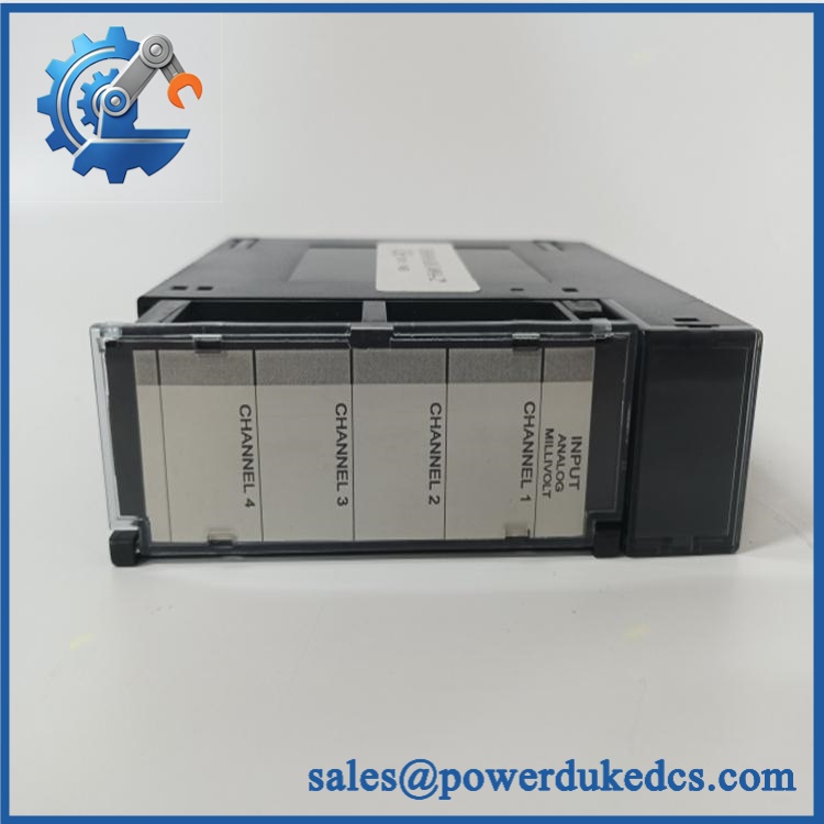
GE HE693ADC409A-22
Quality Assurance & Testing SOP
Part-number verification: Confirm the physical identification as HE693ADC409A-22 and record manufacturer marking, revision, serial number, and visible ordering information. A unit identified only as should not be released without suffix verification.
OEM anti-counterfeit visual inspection: Compare housing, PCB construction, labels, connector arrangement, component population, and identifying markings against the verified reference. Any inconsistent label, unexplained PCB rework, substituted component, or damaged identification requires manual review.
Mechanical inspection: Check the enclosure, PCB, terminal strip, mounting hardware, and connector interface for cracks, corrosion, contamination, bent contacts, loose hardware, and evidence of thermal damage.
Terminal inspection: Examine all positions of the removable 20-pin terminal strip. Verify contact condition and retention, with particular attention to signs of oxidation or previous field over-tightening.
Configuration capture: Record input-range and filtering settings from the existing module where accessible. Photograph terminal wiring and label each field circuit before removal.
Power-on self-test (POST): Install the module in an approved Series 90-30 test rack and apply controlled power. Verify module initialization, PLC recognition, and normal diagnostic behavior.
Millivolt signal simulation: Apply calibrated millivolt signals to each of the four channels across representative points within the documented ±250 mV, ±500 mV, and ±1 V ranges. Compare measured input values against the reference source and verify consistent channel response.
Resolution and scaling verification: Confirm that the 14-bit conversion produces stable, repeatable digital values in the PLC analog input table. Check zero, mid-scale, and upper-range values for each configured channel.
Load-cell / strain-gauge simulation: Where the test fixture supports it, connect a calibrated bridge simulator or appropriate strain-gauge source. Verify expected signal response without introducing excessive external excitation or unsupported loads.
I/O load testing: Run all four analog channels simultaneously with representative signals and monitor for intermittent readings, channel drift, conversion errors, or abnormal PLC diagnostics.
Filter verification: Test the configured digital filtering setting with a controlled changing input and verify that the resulting PLC value follows the approved filtering behavior without unexpected channel instability.
Electrical checks: Verify the 5 VDC module supply and inspect for abnormal current draw during operation. The -22 documentation specifies approximately 100 mA at 5 VDC.
Final QA release: Record exact model, revision, serial number where available, input-range configuration, terminal inspection, POST result, four-channel signal-test results, calibration reference, technician, and test date. Approved units are stored and shipped using ESD protection.
Procurement & Lifecycle FAQ
Is the genuinely in stock and what is the cutoff for emergency shipping?
Current industrial inventory listings show units being offered for sale, including listings described as available from stock. Online listings do not establish a supplier’s real-time physical quantity, so the actual unit, suffix, condition, and shipping cutoff should be confirmed before an emergency PO is released.
How do you verify the condition and authenticity of an obsolete or legacy ?
Require exact part-number verification on the physical unit, followed by label and PCB inspection, terminal inspection, configuration capture, controlled rack power-up, and calibrated four-channel millivolt testing. The commercial condition should be stated as New Surplus, Tested Surplus, or Tested Refurbished rather than using a generic condition description.
Are there any firmware compatibility issues I should warn engineers about before issuing the PO?
No routine firmware-flash requirement is identified in the reviewed -22 documentation. The more important compatibility issue is the module configuration. The A-22 documentation specifies selectable ±250 mV, ±500 mV, and ±1000 mV ranges and software/HHP configuration, so engineers should verify the installed application settings before startup.
Is the a direct replacement?
For an existing , an exact same-model unit can generally be treated as a drop-in replacement with no planned hardware modification. The replacement still requires verification of the input range, terminal wiring, filtering, and PLC configuration. A base or a different suffix should not be accepted solely because the family number appears similar, since the documented electrical ranges can differ materially.
What warranty and return terms should procurement require?
The PO should specify the exact part number, manufacturer marking, revision where applicable, condition category, test status, warranty period, DOA definition, return period, and return-freight responsibility. Retaining actual-unit identification photographs and the pre-shipment test report is advisable for legacy PLC spare-part purchases.











 Start Chat


