

Description
- Brand: GE Fanuc / GE
- Full Model Number: IC200CHS001
- System/Series Family: VersaMax Modular I/O
- One-Sentence Core Function: Local barrier-style I/O carrier providing module mounting, backplane communications, and integrated field wiring for one VersaMax I/O module
- Top 3 Hardcore Specs: 36 barrier-style terminals; up to 32 I/O points; DIN-rail mounting
- Wiring Range: AWG 22–14
- Current Per Point: Up to 2 A
- Voltage Rating: Up to 264 VAC
- Stock Status: New Surplus / Fully Tested Refurbished subject to actual inventory inspection
Module 3: Commercial-Technical Deep Dive
A damaged I/O carrier can interrupt field wiring even when the VersaMax electronics module itself is fully functional. The GE IC200CHS001 is the VersaMax local barrier-style I/O carrier, providing the physical mounting interface, backplane communications, and integrated field terminals for one VersaMax I/O module. GE’s VersaMax documentation identifies IC200CHS001 as one of the standard I/O carriers required by VersaMax modular I/O configurations, while the carrier specification identifies 36 barrier-style terminals and support for up to 32 I/O points plus four common/power connections.
The practical benefit is straightforward: field wiring remains landed on the carrier while the active I/O module can be removed or replaced without rebuilding the entire terminal arrangement. The carrier mounts to a 35 mm DIN rail, and published specifications permit AWG 22–14 conductors with a stated maximum of 2 A per point and 264 VAC maximum voltage rating. GE VersaMax documentation also describes the carrier system as supporting module hot insertion and removal, although whether online removal is acceptable depends on the specific I/O module, process, and site procedure.
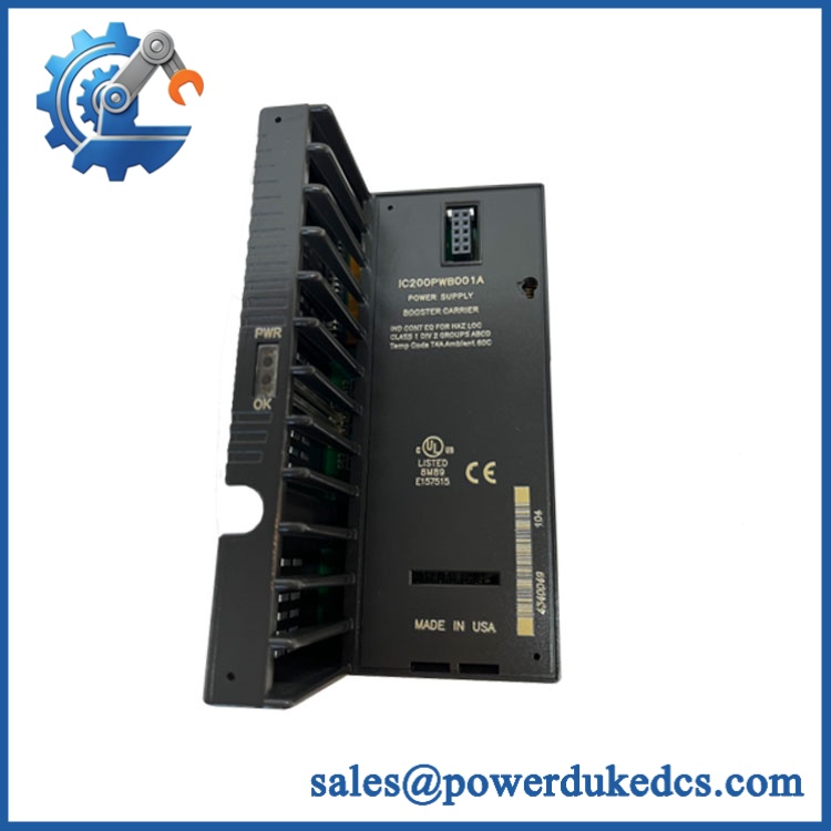
GE IC200CHS001
Module 4: Compatibility & Installation Traps
Migration/Compatibility
- Replacement status: GE Fanuc VersaMax local barrier-style I/O carrier
- Logic rewrite: Not required. The carrier provides mounting, wiring, and backplane interconnection rather than application logic.
- Firmware flash: Not applicable to the passive carrier.
- Drop-in status: Direct replacement is generally practical when the existing installation uses the same IC200CHS001 carrier generation and compatible VersaMax I/O module.
- Field termination: 36 integrated barrier-style terminals.
- Capacity: Up to 32 I/O points plus four common/power connections.
- Mounting: 35 mm DIN rail.
- Carrier compatibility: GE guidance states that all VersaMax I/O modules require an appropriate I/O carrier, including IC200CHS001, CHS002, CHS003, CHS005, CHS022, or CHS025 depending on the installation.
⚠️ Field Traps (Watch Out)
- Carrier revision matters: Barrier-style carrier Version A has documented exclusions for certain high-isolation modules, including the IC200MDL144, IC200MDL244, and IC200MDD850. Version B and later are identified as compatible with all VersaMax I/O module types. Verify the carrier revision before replacing it.
- Terminal rewiring risk: The carrier contains the actual field terminals. Label each conductor before removal and preserve terminal numbering; a carrier replacement can become a wiring fault if conductors are moved one position off.
- DIN-rail grounding: The VersaMax documentation recommends grounding the DIN rail for EMC performance. Verify that the rail provides a conductive, corrosion-resistant connection to protective earth.
- Current and voltage limits: Do not use the published 2 A per point / 264 VAC limits as a substitute for the rating of the installed I/O module. The carrier’s wiring capacity does not automatically increase the electrical rating of the module.
- Hot-insertion assumption: VersaMax carriers support hot insertion/removal, but the connected process may not. Disable or isolate affected field outputs before removing a module or carrier.
Module 5: Quality Assurance SOP
Before shipment, the GE IC200CHS001 should undergo a carrier-specific inspection:
- OEM anti-counterfeit visual inspection — verify GE/GE Fanuc identification, marking, PCB identification, terminal layout, housing geometry, and manufacturer markings.
- Revision verification — identify the carrier revision, especially when the replacement is intended for high-isolation VersaMax I/O modules.
- Mechanical inspection — inspect the DIN-rail latch, module locking features, terminal barrier, hinged transparent terminal cover, connectors, and mounting points.
- Terminal inspection — inspect all 36 barrier terminals for damage, stripped threads, corrosion, contamination, or recessed contacts.
- Continuity verification — test representative terminal-to-backplane paths against the applicable carrier documentation.
- Terminal torque inspection — verify that terminals can securely accept the specified field wiring and that no terminal hardware is damaged.
- Module-interface verification — install a compatible VersaMax I/O module and confirm proper mechanical seating and backplane connection.
- Backplane communication test — connect the carrier to a suitable VersaMax CPU/NIU test environment and verify that the installed I/O module is recognized.
- Field-signal continuity test — inject controlled signals through representative terminal points and confirm correct transmission to the I/O module.
- DIN-rail retention test — verify secure mounting and locking action without excessive mechanical play.
- Final QC record — document exact part number, carrier revision, terminal inspection, test module, communication result, photographs, and packaging condition.
For an I/O carrier, visual appearance is not enough. Terminal integrity, backplane continuity, mechanical retention, and successful I/O communication are the useful acceptance criteria.
Module 6: CRO-Driven Buyer FAQ
1. Is GE obsolete, and how do I verify an authentic replacement?
is a legacy VersaMax I/O carrier, but current technical references still identify the exact catalog number and its barrier-style function. GE documentation also distinguishes carrier revisions, which matters for certain high-isolation I/O modules. For procurement, verify the complete number and carrier revision rather than buying a generic VersaMax base.
2. Can I hot-swap the ?
VersaMax documentation describes the carrier system as supporting hot insertion and removal of modules, but this does not mean every field circuit is safe to disturb while energized. Isolate outputs and field energy according to the I/O module and process-maintenance procedure before removing a carrier or its connected module.
3. Does replacing require PLC programming?
No. The carrier is a passive interconnection and field-wiring component. After replacement, verify terminal continuity, module recognition, I/O addressing, and field signal operation; the PLC program itself normally does not need to be rewritten.
4. How many terminals and I/O points does support?
The carrier provides 36 integrated barrier-style terminals and supports up to 32 I/O points plus four common/power connections. Published specifications also list up to 2 A per point and 264 VAC maximum voltage.
5. Can any VersaMax I/O module be installed on ?
Not without checking the carrier revision. GE documentation states that Version B and later barrier-style carriers are compatible with all VersaMax I/O module types, while Version A has exclusions for specific high-isolation AC and mixed I/O modules.
Warranty and Technical Support
Warranty duration should be stated according to the actual inventory condition, such as new surplus or tested refurbished. Technical support should cover exact carrier identification, revision compatibility, terminal mapping, DIN-rail installation, backplane communication, and documented pre-shipment inspection. Field rewiring, energized maintenance, and process-loop commissioning remain the responsibility of qualified automation personnel.











 Start Chat


