

Description
- Brand: GE Fanuc
- Full Model Number: IC200CHS022
- System/Series Family: VersaMax
- Core Function: Compact box-style carrier providing mounting, backplane communication, and field wiring for one VersaMax I/O module
- Top 3 Hardcore Specs: 36 IEC box-style terminals; 0–264 VAC terminal rating; 2 A per point
- Terminal Layout: A1–A18 and B1–B18
- Mounting: 7.5 × 35 mm DIN rail or panel
- Power/Ground Rating: 8 A per power and ground
- Transient Rating: 300 VAC
- Stock Status: New Surplus / Factory-Sealed or Fully Tested Refurbished subject to actual inventory condition
GE’s VersaMax documentation identifies the IC200CHS022 as a compact box-style I/O carrier with 36 IEC box-style terminals, providing mounting, backplane communications, and field wiring for one I/O module.
Module 3: Technical Product Introduction
When a VersaMax I/O assembly has damaged terminals, a broken carrier, or unreliable backplane contact, replacing only the electronic I/O module will not correct the installation. The GE IC200CHS022 is the compact box-style I/O carrier that mechanically supports one VersaMax I/O module while providing its backplane connection and field-wiring termination. It has 36 IEC box-style terminals, arranged as A1–A18 and B1–B18, and the I/O module mounts vertically relative to the DIN rail.
The carrier is designed for practical cabinet installation. It can snap onto a 7.5 × 35 mm DIN rail or be panel mounted, with terminals rated up to 2 A per point, 8 A for each power and ground connection, and up to 264 VAC. The documented transient rating is 300 VAC. For wiring, one solid or stranded conductor from approximately AWG 14 through AWG 22 can be accommodated; two conductors can be used when they are both AWG 18 and of the same type.
Module 4: Application Scenarios & Field Realities
- Inside a VersaMax PLC cabinet, the IC200CHS022 provides the physical carrier between the I/O module and the field wiring. If an I/O module appears electrically healthy but several field points become intermittent simultaneously, inspect the carrier and backplane connection before replacing the electronic module.
- For cabinets using dense field wiring, the 36-terminal arrangement provides direct termination at the carrier. The built-in wiring-card holder is useful during maintenance because the module’s wiring information can remain associated with the terminal assembly.
- Where cabinet vibration is a concern, the DIN-rail mounting arrangement needs attention. GE’s documentation states that the DIN rail must be electrically grounded for EMC protection and specifies a conductive, unpainted, corrosion-resistant rail surface.
- During I/O module replacement, the carrier is particularly valuable because field wiring remains associated with the carrier while the I/O module itself is changed. Do not, however, treat the carrier as electrically universal outside the VersaMax architecture; the backplane interface is specific to the VersaMax I/O system.
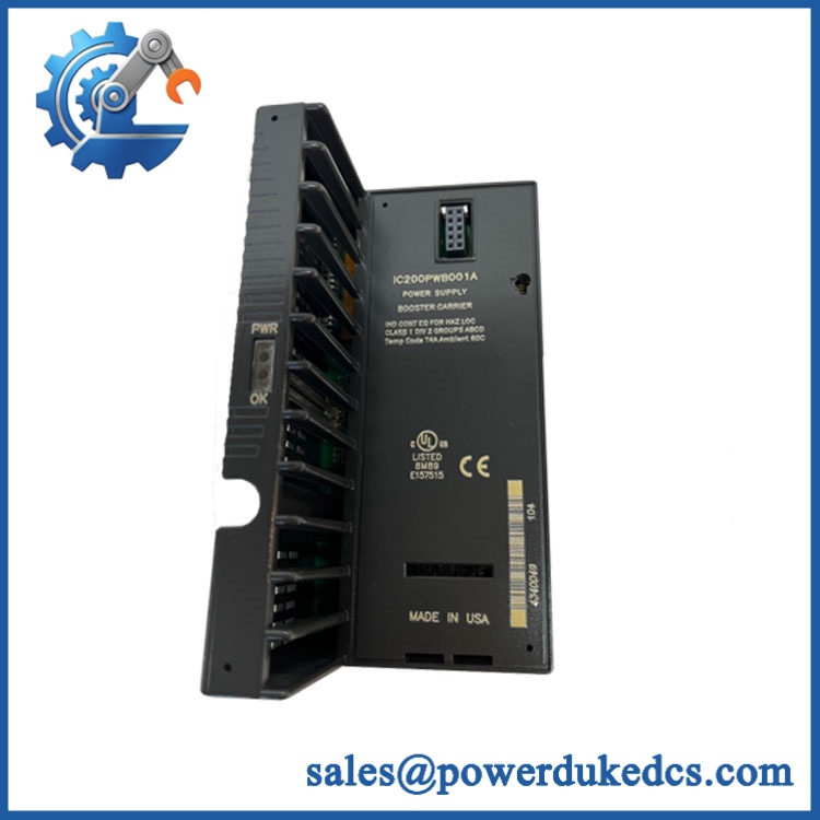
GE IC200CHS022
Module 5: Migration, Compatibility & Installation Traps
Replacement Matrix
| Replacement Case | Classification | Engineering Requirement |
|---|---|---|
| Existing IC200CHS022 replaced with the identical IC200CHS022 | Drop-in Replacement | Verify terminal arrangement, mounting method, and I/O module compatibility |
| IC200CHS022 replaced with another documented VersaMax carrier | Software Compatible | Confirm carrier/module combination and field-terminal arrangement |
| Non-VersaMax carrier substituted | Hardware Modification Required | Mechanical, backplane, and wiring compatibility must be redesigned |
Field Traps — Watch Out
1. Do not confuse the carrier with the I/O module.
The IC200CHS022 does not provide the I/O processing itself. It provides mounting, backplane communication, and field wiring for one VersaMax I/O module. The replacement I/O module still has to be compatible with the carrier and the control-system configuration.
2. Terminal ratings are not the same as module output ratings.
The carrier’s 2 A per point and 8 A power/ground ratings describe the carrier terminals and wiring interface. They should not be interpreted as the current rating of every I/O module installed on the carrier. Check the specific I/O module’s electrical rating separately.
Installation note: GE specifies 0.37–0.45 ft-lb as the recommended terminal torque for the box-style carrier. Use the correct torque rather than tightening terminals by feel, particularly on older field wiring where excessive force can damage conductors or terminal hardware.
Module 6: Quality Assurance SOP
For the GE IC200CHS022, QA should concentrate on terminal integrity, backplane contacts, mechanical fit, and correct VersaMax carrier identification.
- Part-number verification: Confirm IC200CHS022 on the carrier identification marking and purchasing record.
- OEM anti-counterfeit visual inspection: Check GE/GE Fanuc markings, catalog number, molded housing details, terminal construction, labels, and manufacturing markings.
- Mechanical inspection: Examine the carrier body, DIN-rail latch, panel-mount points, terminal strips, card holder, and backplane interface for cracks or deformation.
- Terminal inspection: Check all 36 terminals for corrosion, looseness, damaged threads, cracked insulation, or deformation.
- Backplane contact inspection: Examine the module-to-carrier interface for contamination, oxidation, bent contacts, or physical damage.
- I/O module fit test: Install a compatible VersaMax I/O module and confirm correct mechanical seating and retention.
- Backplane verification: With an appropriate VersaMax test system, verify that the installed I/O module communicates correctly through the carrier.
- Field-terminal continuity verification: Check the relevant terminal paths with suitable low-voltage instrumentation before applying operating voltage.
- Mounting verification: Confirm secure attachment to a 7.5 × 35 mm DIN rail or approved panel mounting arrangement. GE specifies that the DIN rail should provide electrical grounding for EMC protection.
- Terminal torque verification: Confirm field terminals are tightened according to the documented 0.37–0.45 ft-lb range for the box-style carrier.
- Communication handshake verification: Verify the installed I/O module’s backplane communication through the carrier using the appropriate VersaMax controller/test rack.
- Final inspection: Recheck the terminal strips, module latch, card holder, mounting points, and packaging after testing.
- Traceability: Record the exact catalog number, visible revision information where available, test setup, inspection date, results, and condition classification.
Engineering note: The IC200CHS022 is a carrier, not an active PLC CPU or standalone I/O module. For procurement, match the carrier to the customer’s existing VersaMax I/O module and field-wiring arrangement rather than treating “36-terminal PLC carrier” as a sufficient specification.











 Start Chat


