

Description
- Brand: GE / GE Intelligent Platforms
- Full Model Number: IC200PWR012D
- System/Series Family: GE VersaMax Distributed I/O
- Core Function: Isolated power supply for VersaMax CPU, Network Interface Unit, or power-supply booster carrier
- Input: 18–30 VDC, 24 VDC nominal
- Output Rails: 5 VDC and 3.3 VDC
- Total Output Current: 1.5 A maximum
- 3.3 VDC Output: Up to 1.0 A
- 5 VDC Output: Up to 1.5 A minus 3.3 V load
- Input Power: 11 W
- Isolation: 1500 VAC between primary and secondary
- Holdup Time: 10 ms
- Protection: Short circuit, overload, reverse polarity
- Mounting: VersaMax CPU/NIU or power-supply booster carrier
- Stock Status: New Surplus / Fully Tested Refurbished — verify exact D revision and condition before shipment
GE VersaMax documentation identifies IC200PWR012 as the 24 VDC Isolated Power Supply with Expanded 3.3 V output. The documented input range is 18–30 VDC, with 1.5 A maximum total output, up to 1.0 A on the 3.3 V rail, and the balance available on the 5 V rail. The power supply provides 1500 VAC isolation between primary and secondary circuits.
Module 3: Commercial-Technical Deep Dive
When a VersaMax station becomes unstable after a power fault, the CPU is not necessarily the problem. The GE IC200PWR012D is the enhanced isolated power-supply version of the VersaMax PWR012 family, supplying the internal 5 VDC and 3.3 VDC rails required by the CPU, Network Interface Unit, and I/O modules. GE documentation specifies an 18–30 VDC input, 24 VDC nominal, 11 W input power, and 1.5 A maximum total output current. The enhanced 3.3 V architecture permits up to 1.0 A on the 3.3 V rail, with the remaining capacity available on the 5 V output.
The hard ROI is maintaining electrical isolation between the incoming 24 VDC supply and the VersaMax backplane power domain. GE specifies 1500 VAC isolation, plus short-circuit, overload, and reverse-polarity protection. That matters in cabinets where several I/O stations share field power and where ground-potential differences can otherwise propagate into the control electronics. The supply can also be mounted as the main station supply or as a supplemental source on a power-supply booster carrier. —Do not treat the 1.5 A rating as 1.5 A available separately on both rails; the combined output limit remains 1.5 A.
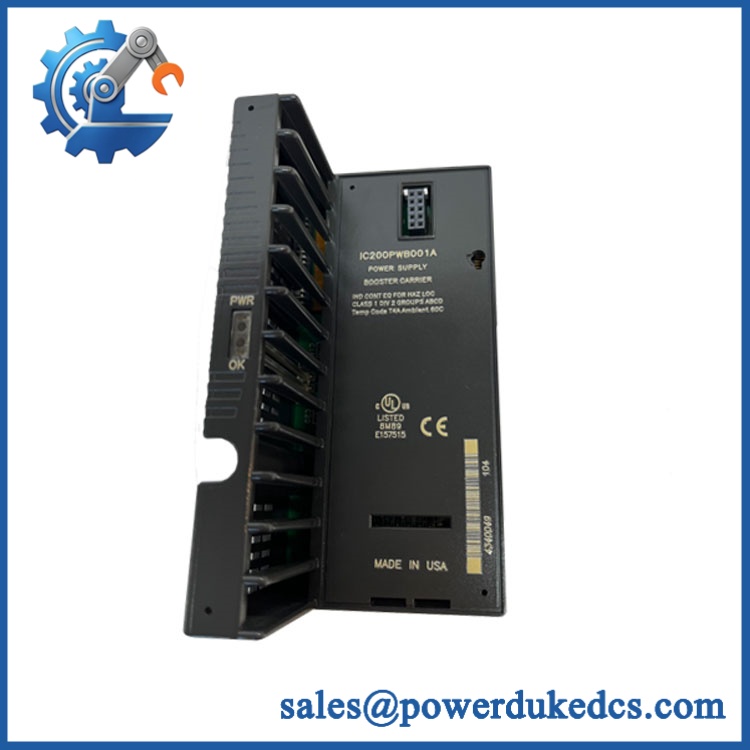
GE IC200PWR012D
Module 4: Compatibility & Installation Traps
Migration/Compatibility
For an existing VersaMax installation specified for IC200PWR012D, the preferred strategy is a like-for-like PWR012 replacement, with the exact revision suffix verified against the installed unit.
No firmware or PLC logic rewrite applies to the power supply itself. The compatibility checks are electrical and mechanical: 18–30 VDC input, isolated 5 V/3.3 V backplane output, total current demand, carrier compatibility, terminal wiring, and the station’s power architecture. GE documentation states that VersaMax power supplies can mount directly on a CPU or Network Interface Unit or onto a power-supply booster carrier.
⚠️ Field Traps (Watch Out)
- Total-current limit: The supply provides 1.5 A maximum combined output, not 1.5 A independently on 5 V and 3.3 V. For example, if the 3.3 V rail draws 0.8 A, only up to approximately 0.7 A remains available on the 5 V rail.
- PWR012 versus PWR011: Both are isolated 24 VDC VersaMax supplies, but PWR012 has the expanded 3.3 V capability of up to 1.0 A, while PWR011 is limited to 0.25 A on 3.3 V. Do not substitute based solely on the word “isolated.”
- Input-range verification: The specified operating input is 18–30 VDC with 24 VDC nominal. A 24 V label on the cabinet does not eliminate the need to verify polarity and actual supply voltage before energizing.
- Carrier compatibility: The PWR012 is not a standalone field power converter. It is designed to mount on a VersaMax CPU, NIU, or power-supply booster carrier. Verify the carrier and station arrangement before installation.
- Backplane-load calculation: Calculate the combined 3.3 V and 5 V demand of every downstream module. A supply can pass a no-load test and still collapse when the actual I/O station is populated.
Module 5: Quality Assurance SOP
- OEM anti-counterfeit visual inspection — verify GE / GE Intelligent Platforms markings, IC200PWR012D identifier, terminal layout, housing, mounting interface, and evidence of unauthorized modification.
- Part-number reconciliation — photograph the complete catalog number, revision suffix, serial information, and all secondary labels.
- Mechanical inspection — check the housing, carrier interface, terminals, mounting latch, and PCB surfaces for cracks, oxidation, contamination, or thermal damage.
- Input verification — confirm the test supply is within the documented 18–30 VDC range before energization.
- Power-on self-test (POST) — energize the unit using a protected laboratory fixture and verify normal startup and output stabilization.
- 5 VDC output test — measure the 5 V rail under no-load and controlled-load conditions.
- 3.3 VDC output test — verify the enhanced up to 1.0 A capability using an appropriate electronic load.
- Combined-load test — test the 5 V and 3.3 V outputs simultaneously while keeping total current at or below the documented 1.5 A limit.
- Isolation verification — where the approved laboratory procedure permits, verify the specified isolation between the 24 V input and the secondary/backplane circuits. GE documents 1500 VAC isolation.
- Protection-function verification — test applicable overload, short-circuit, and reverse-polarity protection using controlled equipment and manufacturer-approved limits.
- Station integration test — install the power supply on a representative VersaMax CPU/NIU or booster-carrier assembly and confirm stable operation with representative I/O load.
- Holdup verification — where supported by the test fixture, verify the documented 10 ms holdup time under the approved load condition.
- Thermal stability observation — operate the supply under representative load and record voltage stability, temperature rise, and any intermittent behavior.
- Final QC release — retain identification photographs, input/output measurements, isolation results, load-test records, and packaging inspection documentation.
For a VersaMax power supply, a single 5 V measurement is only a preliminary check. The meaningful acceptance test covers both rails, combined loading, isolation, protection behavior, and stable operation on the representative station.
Module 6: CRO-Driven Buyer FAQ
1. What is GE IC200PWR012D?
It is a GE VersaMax 24 VDC isolated power-supply module with expanded 3.3 V capability. The PWR012 family provides 5 VDC and 3.3 VDC backplane power, with a 1.5 A maximum combined output and up to 1.0 A on the 3.3 V rail.
2. What input voltage does IC200PWR012D require?
The documented input range is 18–30 VDC, with 24 VDC nominal operation. Verify both polarity and actual measured cabinet voltage before connecting the module.
3. What is the difference between IC200PWR012 and IC200PWR011?
Both are isolated 24 VDC VersaMax power supplies, but is the enhanced version, permitting up to 1.0 A on the 3.3 V output. PWR011 is limited to 0.25 A on 3.3 V. The combined output-current limit remains 1.5 A for both.
4. Can be hot-swapped?
Do not assume hot-swap capability. The power supply feeds the VersaMax backplane and is connected to the station’s 24 VDC source. Follow the applicable VersaMax maintenance procedure and electrical-isolation requirements before removal.
5. Does require firmware or PLC programming?
No. It is a fixed-function power module. After replacement, verify the 5 V and 3.3 V rails under representative station load and confirm that the CPU, NIU, and I/O modules start normally.
6. What warranty and technical support should I expect?
The quotation should state whether the module is new surplus, unused, or tested refurbished and specify the warranty period. Technical support should cover exact-part verification, revision identification, carrier compatibility, output-load testing, isolation verification, and QC records. PLC application changes and station commissioning should remain separate engineering activities.











 Start Chat


