

Description
- Brand: GE Fanuc
- Full Model Number: IC200PWR101D
- System/Series Family: VersaMax Modular I/O / PLC
- One-Sentence Core Function: AC-powered backplane supply providing 5 VDC and 3.3 VDC power to VersaMax CPUs, NIUs, and I/O modules
- Top 3 Hardcore Specs: 85–132 VAC / 176–264 VAC input; 5 VDC + 3.3 VDC output; 1.5 A total output
- Nominal Input: 120 VAC or 240 VAC
- Input Frequency: 47–63 Hz
- Input Power: 27 VA
- Output Current: 1.5 A maximum combined
- 3.3 VDC Output: 0.25 A maximum
- 5 VDC Output: Up to 1.5 A minus 3.3 VDC load
- Holdup Time: 20 ms
- Protection: Short circuit and overload
- Installation: VersaMax CPU, NIU, or power-supply booster carrier
- 120 VAC Selection: Jumper installed
- 240 VAC Selection: Jumper removed
- Stock Status: New Surplus / Factory Sealed / Fully Tested Refurbished subject to availability
GE VersaMax documentation identifies the IC200PWR101 family as a 120/240 VAC power supply for CPU, NIU, and I/O backplane power. The published specification is 85–132 VAC with the 120 V jumper installed, 176–264 VAC with the jumper removed, 27 VA input power, 20 ms holdup, and 1.5 A maximum combined output through the 5 VDC and 3.3 VDC rails.
Module 3: Commercial-Technical Deep Dive
A VersaMax rack can lose multiple PLC and I/O functions from one power-supply failure, even when the CPU and field modules themselves are healthy. The GE IC200PWR101D is the AC-input power supply for the VersaMax platform, supplying the rack backplane with both 5 VDC and 3.3 VDC. GE specifies up to 1.5 A total output current, with the 3.3 VDC rail limited to 0.25 A; the available current on the 5 VDC rail is therefore the 1.5 A total minus whatever the 3.3 VDC rail consumes. It can serve as the primary supply when mounted on a CPU or NIU and as a supplemental supply when installed on a VersaMax power-supply booster carrier.
The input-selection detail is where field mistakes usually happen. GE specifies 85–132 VAC for nominal 120 VAC operation when the jumper is installed, and 176–264 VAC for nominal 240 VAC operation with the jumper removed. Input frequency is 47–63 Hz, input power is 27 VA, and holdup time is 20 ms. The supply also includes short-circuit and overload protection. The D revision should still be matched from the physical nameplate, because VersaMax supplies exist in several revisions even though the published IC200PWR101 family electrical specification remains the key reference.
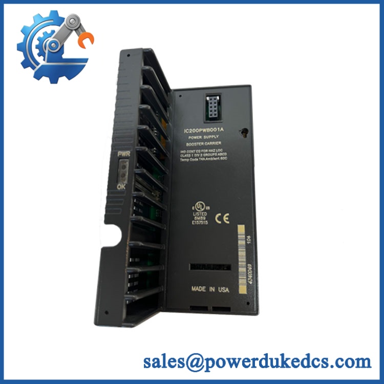
GE IC200PWR101D
Module 4: Compatibility & Installation Traps
Migration/Compatibility
- System: GE VersaMax Modular I/O / PLC
- Full Model: IC200PWR101D
- Base Family: IC200PWR101
- Power Type: 120/240 VAC input
- Nominal Input: 120 VAC / 240 VAC
- Input Range: 85–132 VAC with jumper; 176–264 VAC without jumper
- Frequency: 47–63 Hz
- Output Rails: 5 VDC and 3.3 VDC
- Total Output: 1.5 A maximum
- 3.3 VDC Limit: 0.25 A maximum
- Primary Use: CPU/NIU backplane power
- Supplemental Use: VersaMax power-supply booster carrier
- Replacement Type: Exact IC200PWR101D revision preferred
- Application Check: Calculate total VersaMax backplane current before substitution
- Logic Rewrite: Not applicable to the power supply itself; the PLC application normally remains unchanged
⚠️ Field Traps (Watch Out)
1. The 120/240 VAC jumper position is critical.
GE specifies the lower AC range with the jumper installed and the higher range with the jumper removed. The manual explicitly shows the jumper selection as part of installation. Verify the incoming voltage before changing the jumper; do not treat it as a convenient field selector.
2. Do not exceed 1.5 A combined output.
The 5 VDC and 3.3 VDC rails share the total output budget. For example, if the 3.3 V rail requires 0.25 A, only 1.25 A remains available on the 5 V rail. This matters when a VersaMax rack contains a CPU plus multiple communication or I/O modules.
3. Check the chassis role before installation.
IC200PWR101 can operate as the primary supply on a CPU or NIU and as a supplemental source on a booster carrier. The mounting location therefore affects the role it plays in the station power architecture.
4. Do not assume a larger power supply can replace it without reviewing the backplane architecture.
A different VersaMax supply may have a different 3.3 V capability, input arrangement, or carrier requirement. Match the actual station configuration rather than selecting a substitute from output current alone.
5. Hazardous-location work requires power removal.
The GE VersaMax documentation warns that power should be turned off before replacing or wiring modules in hazardous locations.
Module 5: Quality Assurance SOP
Each available GE IC200PWR101D should undergo a documented power-supply inspection and functional test before shipment:
- OEM anti-counterfeit visual inspection: Verify GE Fanuc / VersaMax markings, complete IC200PWR101D designation, terminal labels, jumper marking, housing, and manufacturing identifiers.
- Revision verification: Record the physical revision suffix and compare it with the requested D version.
- Mechanical inspection: Check the housing, terminal block, mounting interface, jumper location, carrier connector, and enclosure for cracks or deformation.
- PCB condition inspection: Inspect accessible electronics for corrosion, contamination, cracked components, thermal discoloration, damaged traces, and prior repair evidence.
- Input precheck: Verify resistance and continuity before applying AC power.
- Jumper verification: Record the 120/240 VAC jumper position before energization.
- Power-on self-test (POST): Apply a controlled input within the applicable AC range and verify normal startup and output-rail behavior.
- 120 VAC test: With the approved jumper configuration, verify stable 5 VDC and 3.3 VDC outputs under controlled load.
- 240 VAC test: With the jumper removed as required, verify stable operation at nominal 240 VAC.
- Output-current test: Load the combined DC outputs within laboratory limits and confirm the 1.5 A total maximum is respected.
- 3.3 VDC verification: Confirm the 3.3 VDC rail operates correctly under representative loading up to the documented 0.25 A maximum.
- 5 VDC verification: Confirm the 5 VDC rail remains within the approved tolerance while the 3.3 VDC rail is loaded.
- Holdup test: Verify the documented approximately 20 ms ride-through behavior where the laboratory fixture supports controlled input interruption.
- Protection test: Perform controlled overload or short-circuit testing only within the approved laboratory procedure; verify recovery without exceeding safe equipment limits.
- Backplane integration test: Install the supply on an approved VersaMax CPU/NIU or booster-carrier fixture and verify stable rack power with representative module loading.
- Thermal observation: Monitor supply temperature during sustained operation and document abnormal heating.
- Final QC record: Record catalog number, revision, jumper state, AC input, 5 VDC measurement, 3.3 VDC measurement, load conditions, holdup result, and technician sign-off.
- ESD-safe packaging: Protect the power supply and carrier connector against electrostatic discharge, impact, and terminal damage.
The best outgoing test report should show input voltage, jumper state, 5 VDC output, 3.3 VDC output, and actual load current. “Power tested” is too vague for a dual-rail VersaMax supply because an apparently normal 5 V rail can still hide a 3.3 V rail or capacity problem.
Module 6: CRO-Driven Buyer FAQ
What is GE ?
GE is a VersaMax 120/240 VAC power supply module in the IC200PWR101 family. It provides 5 VDC and 3.3 VDC power to the VersaMax backplane for CPUs, NIUs, and I/O modules.
What is the input voltage range of ?
The IC200PWR101 family accepts 85–132 VAC with the 120 V jumper installed and 176–264 VAC with the jumper removed. Nominal inputs are 120 VAC and 240 VAC respectively. The specified frequency range is 47–63 Hz.
How much DC power can supply?
The combined 5 VDC and 3.3 VDC output is limited to 1.5 A. The 3.3 VDC rail can provide up to 0.25 A, with the remaining capacity available to the 5 VDC rail.
Can power a complete VersaMax station?
Yes, within its current limits. GE describes it as the main station supply when mounted on a CPU or NIU and as a supplemental supply when mounted on a power-supply booster carrier. The actual rack load should be calculated from the installed CPU, NIU, communication, and I/O modules before commissioning.
What is the difference between and IC200PWR102?
They are different VersaMax AC power-supply families. is the standard 120/240 VAC supply with 1.5 A total output and 0.25 A maximum on 3.3 V, while IC200PWR102 is the expanded-3.3 V version. Do not substitute between them without checking the rack’s 3.3 V power requirement.
Can be replaced while the VersaMax system is powered?
Do not assume live replacement is permitted. The module carries hazardous AC input and supplies the backplane rails used by the controller and I/O. Follow the GE VersaMax installation procedure and site electrical-isolation requirements before removal.
What should I verify before ordering ?
Confirm the complete revision, incoming 120/240 VAC level, jumper arrangement, station power demand, CPU/NIU mounting position, booster-carrier use, and required 3.3 VDC current. A photo of the existing nameplate and jumper configuration is useful for exact replacement matching.
What warranty and technical support should I expect?
Warranty duration should be stated for the exact unit condition and test status on the quotation. Technical support should cover part-number and revision verification, input-voltage/jumper checks, VersaMax carrier compatibility, backplane power calculations, and documented dual-rail testing. PLC application changes and field commissioning should be treated separately unless explicitly included.











 Start Chat


