

Description
- Brand: GE Fanuc
- Full Model Number: IC660BBA104K
- System/Series Family: GE Genius I/O
- One-Sentence Core Function: Isolated current-source analog I/O block for four 4–20 mA inputs and two 4–20 mA outputs on a Genius Bus network
- Top 3 Hardcore Specs: 4 analog inputs + 2 analog outputs; 4–20 mA signal range; 115 VAC / 125 VDC block power
- Stock Status: New surplus / fully tested refurbished
The GE IC660BBA104K is a Genius analog current-source I/O block providing four 4–20 mA inputs and two 4–20 mA outputs. GE’s Genius I/O manual identifies the IC660BBA104 family as a 115 VAC/125 VDC current-source analog 4-input/2-output block, with isolated circuits and self-powered 4–20 mA signal interfaces.
The K suffix is significant. Current technical documentation identifies IC660BBA104K as revision K, and revision information notes that revision K and later use the newer electronic housing, which can require the corresponding newer-style plastic door and may create terminal-strip compatibility considerations.
Module 3: Commercial-Technical Deep Dive
A failed analog block can remove several process measurements and control outputs from a Genius network simultaneously. The GE IC660BBA104K handles four 4–20 mA analog input channels and two 4–20 mA analog output channels, with the block itself supplying power for the current-loop circuitry. Input channels include diagnostics for open-wire, high/low alarm, overrange, and underrange conditions; output channels provide feedback monitoring and overrange/underrange diagnostics. That combination makes the block useful for distributed measurement and control where pressure, temperature, flow, level, valve, or actuator signals remain on legacy Genius I/O.
The technical numbers explain its maintenance value. Input accuracy is specified at approximately 0.1% of full scale, with 1 µA input resolution; input conversion time is configurable from 16.6 ms to 400 ms. The two outputs provide approximately 0.15% full-scale accuracy, 6 µA output resolution, and a typical 6–8 ms update time. The block accepts 93–132 VAC or 105–145 VDC operating power from its nominal 115 VAC/125 VDC supply. For a replacement unit, these figures translate directly into signal compatibility—though the process transmitter, output load, Genius bus configuration, and exact revision still need to match the installed application.
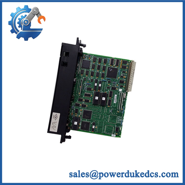
GE IC660BBA104K
Module 4: Compatibility & Installation Traps
Migration/Compatibility
- Replacement type: GE Genius current-source analog I/O block
- Model: IC660BBA104K
- I/O configuration: 4 analog inputs / 2 analog outputs
- Signal range: 4–20 mA
- Block power: 115 VAC / 125 VDC nominal
- Firmware flash: Not normally required for a same-revision hardware replacement; configuration must still be verified
- Logic rewrite: Normally not required
- Drop-in status: Potentially direct when the Genius bus configuration, terminal assembly, power supply, and revision match
- Configuration tool: GE documentation identifies Hand-Held Monitor version 3.7 or later for configuration of the IC660BBA104 family.
- Network: Genius Bus communication
- Related bus hardware: Compatible with Genius Bus Controllers and PCIM/QBIM interfaces.
⚠️ Field Traps (Watch Out)
1. Revision K is not merely a cosmetic suffix.
Revision information identifies IC660BBA104K as a K-revision unit using the newer electronic housing. The newer housing can require a corresponding plastic door and may introduce terminal-strip compatibility considerations. Confirm the terminal assembly before treating a lower-revision IC660BBA104 as an exact mechanical replacement.
2. Verify the 115 VAC / 125 VDC power circuit.
The block is nominally rated for 115 VAC or 125 VDC, with documented input ranges of approximately 93–132 VAC / 105–145 VDC. Do not apply a 24 VDC supply used by other Genius I/O components simply because the station contains mixed-voltage hardware.
3. Protect the 4–20 mA loop wiring.
The inputs are current-source interfaces and the block provides power for the signal circuits. Confirm transmitter polarity, loop wiring, grounding, and the actual field transmitter arrangement before energizing the block.
4. Check output loading and feedback wiring.
The two analog outputs are 4–20 mA channels with output feedback diagnostics. Verify the receiving device’s input impedance and wiring before commissioning. A loop fault can be reported as an output problem even when the block electronics are healthy.
5. Do not overlook the Genius bus address and configuration.
A physically correct analog block can remain offline if its Genius network configuration does not match the original station. Preserve the original configuration before replacement and verify the block’s network identity after installation.
Module 5: Quality Assurance SOP
Each GE unit should pass a documented pre-shipment inspection sequence:
- OEM anti-counterfeit visual inspection: Verify GE Fanuc identification, , revision marking, terminal layout, housing style, LEDs, and manufacturing labels.
- Exact part-number verification: Match the complete K-revision catalog number against the purchase order and installed Genius I/O BOM.
- Housing/revision inspection: Confirm the newer K-revision housing and verify the associated door/terminal arrangement before release.
- Mechanical inspection: Check the 32-terminal assembly, terminal screws, housing, mounting hardware, indicator panel, and accessible PCB areas for cracks, corrosion, contamination, or unauthorized repair.
- Power-input inspection: Verify the block power terminals and inspect for damaged contacts, overheating, or loose hardware.
- Power-on self-test (POST): Install the block in an approved Genius test environment and verify expected power, communication, and diagnostic indicators.
- Analog-input verification: Apply calibrated 4–20 mA signals to all four input channels and verify measured values, scaling, alarm thresholds, and open-wire behavior.
- Analog-output verification: Command each of the two 4–20 mA outputs across representative points and measure actual loop current with calibrated equipment.
- Diagnostic verification: Exercise controlled overrange, underrange, and output-feedback fault conditions where the test fixture permits, confirming expected diagnostic response.
- Genius communication handshake verification: Confirm the block communicates correctly with a compatible Genius Bus Controller and that input/output data is transferred without persistent communication faults.
- Configuration verification: Confirm the network address, scaling parameters, alarm behavior, output-state behavior, conversion settings, and other retained configuration values.
- Final QC: Record serial/revision information, analog-channel test results, Genius bus test results, and configuration status; photograph the nameplate and package the unit in ESD-safe protective material.
Module 6: CRO-Driven Buyer FAQ
1. What is GE ?
The is a GE Fanuc Genius current-source analog I/O block with four 4–20 mA analog inputs and two 4–20 mA analog outputs. It is part of the Genius distributed I/O architecture.
2. What power supply does require?
The block uses a nominal 115 VAC / 125 VDC power supply. The documented operating ranges are approximately 93–132 VAC or 105–145 VDC.
3. What does the K suffix mean?
The K revision identifies a later housing revision. Current revision documentation notes that K and later versions use the newer-style electronic housing and can require the corresponding newer plastic door, with possible terminal-strip compatibility considerations.
4. How accurate are the analog channels?
The documented input accuracy is approximately 0.1% of full scale, with 1 µA resolution. Output accuracy is approximately 0.15% of full scale, with 6 µA resolution. Input conversion time is user-selectable from approximately 16.6 ms to 400 ms.
5. Can be hot-swapped?
Do not assume hot-swap capability. The block carries its own AC/DC power and field 4–20 mA circuits, so replacement should follow the applicable GE Genius I/O maintenance procedure with the station isolated before wiring or module removal.
6. What warranty and technical support are provided?
Warranty duration should be stated on the quotation for the exact inventory condition supplied. Technical support should cover revision identification, terminal/housing compatibility, Genius bus configuration, analog-channel testing, scaling verification, and inspection records. Field transmitter wiring, process-loop commissioning, and energized electrical work remain the responsibility of qualified personnel.











 Start Chat


