

Description
- Brand: GE / GE Fanuc
- Full Model Number: IC670CBL001
- System/Series Family: GE Field Control / Genius Distributed I/O
- Core Function: Inter-base connection cable for linking Field Control I/O terminal blocks
- Cable Type: I/O Base Connection Cable
- Quantity: Set of 3 cables
- Primary Connection: Between adjacent Field Control terminal blocks
- Connector: Keyed connectors for correct orientation
- Standard Cable: Short inter-base cable
- Related Long Cable: IC670CBL002, 21 in / 0.53 m
- Application: Genius BIU and Field Control I/O terminal-block networks
- Status: Legacy / Replacement Inventory
- Stock Status: New Surplus / Fully Tested — verify package quantity and connector condition before shipment
GE Fanuc documentation identifies IC670CBL001 as a set of three I/O Base Connection Cables used with Field Control terminal blocks. The standard short cable is supplied with each I/O terminal block, while IC670CBL002 is the optional 21-inch / 0.53 m cable. The connectors are keyed to help prevent incorrect installation.
Module 3: Commercial-Technical Deep Dive
A Field Control station can have every I/O module electrically healthy and still lose the downstream devices because an inter-base cable has a broken conductor, damaged connector, or incomplete engagement. The GE IC670CBL001 is the dedicated connection cable set used to link Field Control I/O terminal blocks within the GE Genius distributed-I/O architecture. GE documentation specifies this part as a three-cable renewal set, while the standard short cable is supplied with each I/O terminal block. The same documentation shows the cable connecting a Bus Interface Unit terminal block to an adjacent I/O terminal block and then continuing the inter-base connection through the station.
The commercial value is simple but significant: restoring the original physical network topology without fabricating an unofficial replacement cable. Because the connectors are keyed, correct orientation is mechanically guided, but that does not eliminate the need to verify full insertion and connector retention. GE specifically instructs technicians to ensure the cable is firmly seated on both connectors after installation. The optional IC670CBL002 provides a much longer 21-inch / 0.53 m connection, while IC670CBL001 is the standard short renewal set. —Do not substitute the longer cable simply to gain routing flexibility; GE documentation limits use of the 21-inch cable to one per Field Control station.
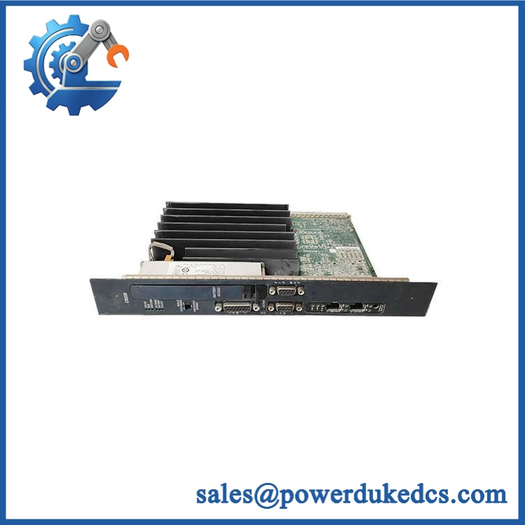
GE IC670CBL001
Module 4: Compatibility & Installation Traps
Migration/Compatibility
For a GE Field Control installation using IC670CBL001, the correct strategy is an exact cable-set replacement using the same keyed connector arrangement and appropriate cable length.
No firmware, PLC logic, or module configuration change is required simply because the inter-base cable is replaced. The critical checks are connector type, cable length, station topology, terminal-block compatibility, and physical routing.
GE documentation identifies IC670CBL001 as a three-cable renewal set and IC670CBL002 as the optional 21-inch cable. This is a physical interconnection component, so exact mechanical and electrical mating matter more than software compatibility.
⚠️ Field Traps (Watch Out)
- Cable-set quantity: is specified as a set of three connecting cables, not simply one generic lead. Verify the supplied quantity before receiving the spare into inventory.
- versus IC670CBL002: The standard CBL001 is the short inter-base cable, while CBL002 is the optional 21-inch / 0.53 m version. GE states that only one longer cable can be used per Field Control station.
- Connector seating: The connectors are keyed, but GE still instructs installers to make sure both ends are firmly seated. A partially engaged connector can create intermittent communication or I/O faults that resemble a defective terminal block.
- Cable routing stress: Do not bend the cable sharply against the connector body or leave it under tensile load. Legacy Field Control terminal blocks rely on these short interconnections for station-to-station continuity.
- Do not power during installation: GE’s Field Control documentation warns against applying power before the appropriate BIU module is installed on its terminal block. Follow the full station installation sequence rather than treating the cable as an isolated accessory.
Module 5: Quality Assurance SOP
- OEM identification inspection — verify GE/GE Fanuc markings and the complete part number.
- Quantity verification — confirm the shipment contains the documented three-cable renewal set.
- Connector inspection — examine all keyed connectors for cracked housings, bent contacts, contamination, damaged locking features, or missing keying components.
- Cable-jacket inspection — check the entire cable length for cuts, abrasion, flattening, chemical damage, or excessive bending.
- Continuity verification — electrically test each conductor from connector to connector using an approved low-voltage continuity fixture.
- Pin-to-pin verification — verify that conductor mapping matches the approved GE cable configuration; do not rely on continuity alone.
- Insulation check — perform an appropriate low-energy insulation-resistance test only under the approved procedure and within the cable assembly’s allowable test limits.
- Connector retention test — mate the cable with representative Field Control terminal blocks and confirm correct keying, full engagement, and mechanical retention.
- Network continuity test — install the cable in a representative Field Control/Genius station and verify communication across the connected terminal blocks.
- Intermittent-fault screening — while monitoring communications, apply controlled mechanical movement to the cable and connectors to identify intermittent contact or conductor faults.
- Final QC release — retain part-number photographs, quantity verification, continuity results, connector inspection results, and packaging records.
For an inter-base cable, a visual inspection cannot establish electrical integrity. The useful acceptance criterion is verified pin-to-pin continuity plus stable communication in a representative Field Control station.
Module 6: CRO-Driven Buyer FAQ
1. What is GE ?
It is a GE Field Control / Genius I/O base connection cable set used to connect adjacent I/O terminal blocks. GE documentation specifies three connecting cables as the renewal part.
2. Is a single cable?
The cataloged renewal part is a set of three cables. A short connecting cable is normally supplied with each I/O terminal block, while provides replacement cables.
3. What is the difference between and IC670CBL002?
is the standard short inter-base cable set. is the optional 21-inch / 0.53 m cable, and GE documentation states that only one longer cable can be used in a Field Control station.
4. Can be used between Genius I/O terminal blocks?
Yes. GE documentation specifically illustrates the cable connecting a Bus Interface Unit terminal block to an I/O terminal block and connecting additional I/O terminal blocks in the same manner.
5. Can be hot-swapped?
Do not assume energized replacement is permissible. The cable is part of an active Field Control/Genius I/O station. Follow the applicable GE installation procedure and remove power before disconnecting or reconnecting the inter-base cable.
6. Does require software configuration?
No. It is a passive interconnection cable assembly. After replacement, the required checks are correct cable routing, full connector engagement, physical continuity, and stable Genius/Field Control communication.
7. What warranty and technical support should I expect?
The quotation should clearly state whether the cable set is new surplus, unused, or tested and specify the warranty period. Technical support should cover exact part-number verification, cable-set quantity, connector compatibility, continuity testing, and documented QC results. Field-control network troubleshooting and plant commissioning should remain separate engineering activities.











 Start Chat


