

Description
- Brand: GE Fanuc
- Full Model Number: IC670MDL930J
- System/Series Family: GE Field Control
- Core Function: Eight-point isolated relay output switching with six Form A contacts and two Form C contacts
- Top 3 Hardcore Specs: 8 isolated relay outputs; 2 A maximum resistive load; 240 VAC / 125 VDC-class contact rating
- Output Configuration: 6 × Form A NO; 2 × Form C NO/NC
- Voltage Range: 5/24/125 VDC; 120/240 VAC
- Frequency: 47–63 Hz for AC
- Maximum Resistive Load: 2 A per contact within rated voltage limits; 16 A module maximum
- Maximum Inrush: 5 A for 20 ms
- Minimum Load: 10 mA per point
- Response Time: 10 ms maximum ON; 10 ms maximum OFF
- Switching Frequency: 20 cycles/minute for inductive load
- Output Protection: RC snubber; no individual fuse
- Contact Type: Silver alloy
- Logic-Side Supply: Bus Interface Unit
- Field Load Supply: External AC/DC source required
- Stock Status: New Surplus or Fully Tested Refurbished; exact revision to be confirmed
GE Field Control documentation identifies IC670MDL930 as a relay-isolated discrete-output module with six Form A and two Form C outputs. Revision J is the hardware revision represented by IC670MDL930J.
Module 3: Technical Product Introduction
A relay-output card becomes valuable when the field circuit needs a true contact interface rather than a transistor output. The GE Fanuc IC670MDL930J is an eight-point isolated relay-output module for the Field Control system. Six channels use normally-open Form A contacts, while two channels use Form C contacts providing both normally-open and normally-closed connections. Each output is isolated from the logic side and requires an external field-power source for the connected load.
The contact ratings are suited to a broad range of auxiliary industrial loads. The module supports 5/24/125 VDC and 120/240 VAC load circuits, with a published voltage range of 0–130 VDC or 0–265 VAC, subject to the individual contact specifications. Maximum resistive load is 2 A per point, with 16 A maximum per module, and maximum inrush is 5 A for 20 ms. Response time is specified at 10 ms maximum for both ON and OFF, while inductive-load switching is limited to approximately 20 cycles per minute.
Module 4: Application Scenarios & Field Realities
- For auxiliary contactor and annunciator circuits, the IC670MDL930J provides a physical relay contact interface that can switch an independently powered field load. This is useful where the receiving circuit requires dry-contact behavior rather than a powered transistor output.
- Where a cabinet requires both NO and NC logic, the two Form C channels can provide a changeover contact arrangement while the other six channels remain normally open. That distinction should be reflected in the wiring drawing before a replacement is installed.
- On mixed-voltage auxiliary circuits, isolated relay contacts permit the field-load supply to remain separate from the module’s internal logic supply. The external load source still has to remain within the applicable contact voltage and current limits.
- During troubleshooting of an apparently failed relay output, inspect the external load supply and field wiring first. The module itself receives operating power from the Field Control Bus Interface Unit, while the switched load power is supplied separately; a missing field supply can therefore look like an output-card failure.
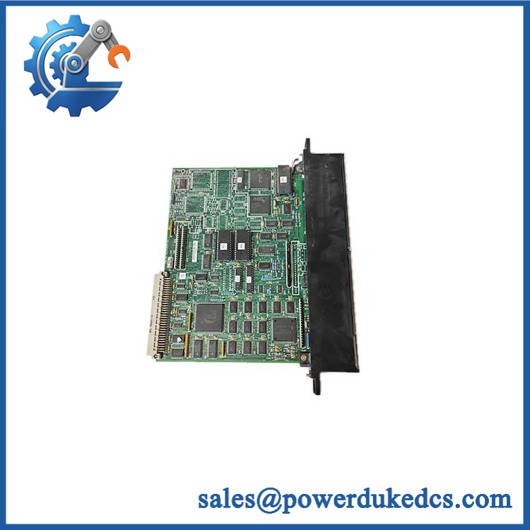
GE IC670MDL930J
Module 5: Migration, Compatibility & Installation Traps
Replacement Matrix
Replacement classification: Drop-in Replacement when the existing Field Control station is configured for IC670MDL930J and the terminal block, keying, field-voltage arrangement, and Bus Interface Unit remain compatible.
Software compatibility: Configuration verification required. The module does not contain the host application logic. Output defaults, fault behavior, channel mapping, and other intelligent functions are handled by the Bus Interface Unit or higher-level system.
Cross-model replacement: Hardware and wiring verification required. IC670MDL930J is not equivalent to a solid-state output module simply because both provide eight discrete outputs. Relay contact form, external power arrangement, load rating, and switching duty all have to match.
Field Traps — Watch Out
1. Do not misidentify the module as a 16-channel relay card. Some secondary listings incorrectly describe as having 16 SPDT outputs. The manufacturer’s-era datasheet identifies the module as 8 points: six Form A plus two Form C. Use the actual module documentation and physical terminal arrangement for engineering records.
2. Check the contact form before moving wires. Six channels are Form A NO contacts, while channels 1C and 2C are Form C changeover contacts. Moving a wire from a Form C terminal to a Form A channel without revising the circuit can invert the intended fail-state behavior.
3. Respect the DC derating. Although the module supports up to 125 VDC, the maximum DC current depends on voltage and load type. A 2 A resistive AC rating should not be copied directly to every DC application.
4. Check the external load supply separately. Module logic power comes from the Bus Interface Unit, while the field load requires an external AC/DC source. Both sides should be verified during commissioning.
5. Watch the inductive switching duty. The relay contacts are rated differently for resistive and reactive loads, and the documented inductive switching frequency is only 20 cycles per minute. A rapidly cycling solenoid or contactor circuit can therefore exceed the intended relay duty even when instantaneous current is below 2 A.
6. Preserve the Field Control terminal-block keying. The module is installed through the Field Control station’s terminal interface. Mechanical keying and terminal assignment need to match the original configuration before insertion.
Module 6: Quality Assurance SOP
Pre-Shipment Inspection Protocol for GE
- OEM identity inspection: Verify GE Fanuc marking, exact designation, hardware revision, serial number, and visible module identification.
- Variant verification: Confirm the module is the eight-point IC670MDL930 family, with six Form A and two Form C relay outputs, rather than a later or incorrectly labeled variant.
- Mechanical inspection: Examine the housing, terminal interface, module keying, LED window, locking features, and accessible PCB areas for cracks, deformation, corrosion, contamination, or unauthorized repair.
- Connector inspection: Check the terminal-block interface and contact areas for oxidation, bent contacts, damaged housings, foreign material, or overheating.
- Relay inspection: Check all eight relay circuits for abnormal contact resistance, evidence of welded contacts, excessive wear, or mechanical sticking.
- Power-on verification: Install the module on a compatible Field Control terminal block and Bus Interface Unit and verify the PWR indication and normal startup behavior.
- Eight-channel verification: Exercise all eight relay outputs independently and record results channel by channel.
- Form A verification: Test the six normally-open outputs for clean closure and release under a controlled low-voltage test load.
- Form C verification: Test both changeover outputs, confirming correct normally-open and normally-closed contact operation independently.
- Contact resistance test: Measure representative closed-contact resistance under an approved low-current test condition and record unstable or excessive values.
- Voltage test: Exercise the relay outputs with representative AC and DC field voltages within the documented operating limits.
- Load test: Apply calibrated resistive loads and verify switching performance up to the applicable current rating without exceeding the contact specification.
- Inrush test: Where the laboratory fixture permits, test controlled load inrush representative of the field application and compare it with the documented 5 A for 20 ms capability.
- Response-time test: Use a controlled timing fixture to verify relay ON and OFF response within the published 10 ms maximum values.
- Inductive-load test: Where required, evaluate the module with a representative approved inductive load and keep the switching rate within the documented duty limitation.
- Snubber inspection: Verify the output protection network is present and intact; the published design uses an RC snubber rather than individual output fuses.
- Isolation verification: Perform an approved isolation test between field circuits and the logic side using the applicable test voltage and safety procedure.
- Host-data verification: Connect the module to a compatible Bus Interface Unit and verify that all eight output states are correctly commanded and reported.
- LED verification: Confirm individual channel LEDs follow the commanded relay states without intermittent operation.
- Repeated-cycle test: Cycle representative outputs under controlled load and inspect for contact bounce, sticking, welded contacts, abnormal heating, or diagnostic instability.
- Thermal observation: Operate representative multiple-channel loads for an extended interval and monitor relay, terminal, and PCB temperatures.
- Final QC record: Record exact model, revision, serial number, terminal block, BIU, contact-form results, voltage/current test data, contact resistance, response time, isolation result, cycle test, test date, and inspector approval.
- ESD and mechanical packaging: Protect the terminal interface, relay assembly, LED panel, and housing against impact, moisture, contamination, vibration, and electrostatic discharge.
Procurement note: The technically supported identity is GE Fanuc — Field Control 8-Point Isolated Relay Output Module. Its defining configuration is six Form A normally-open contacts plus two Form C changeover contacts, with 2 A maximum resistive contact current, 5/24/125 VDC and 120/240 VAC-class load capability, 5 A for 20 ms maximum inrush, 10 ms maximum ON/OFF response, and approximately 20 cycles/minute for inductive loads. The module receives its own operating power from the Bus Interface Unit, while the switched field loads require an external power source.











 Start Chat


