

Description
- Brand: GE Fanuc / GE Intelligent Platforms
- Full Model Number: IC695PSD140A
- Product Type: Power Supply Module
- System/Series Family: PACSystems RX3i
- Core Function: Supplies regulated backplane power to PACSystems RX3i rack components
- Top 3 Hardcore Specs: 120 VAC nominal input | 40 W output | RX3i rack power supply
- Input Voltage: 120 VAC nominal
- Output Power: 40 W
- System Compatibility: PACSystems RX3i
- Stock Status: New surplus / condition to be confirmed per available unit
GE’s IC695PSD140A is an RX3i PACSystems power supply module. The IC695PSD140 family is documented as a rack-mounted power supply, with the PSD140 version associated with 120 VAC input and 40 W output capacity. The module supplies power through the RX3i rack backplane to installed control and I/O modules.
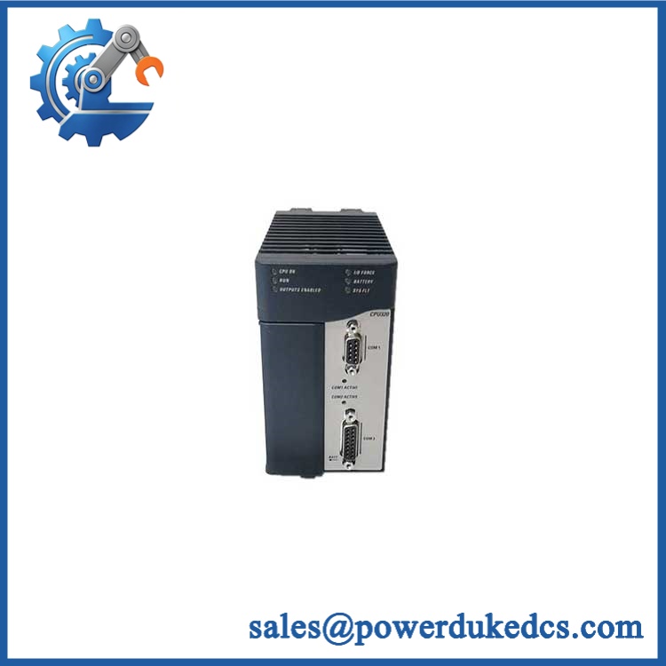
GE IC695PSD140A
Module 3: Technical Product Introduction
A failed rack power supply can make an entire RX3i station appear dead even when the CPU and I/O modules themselves are healthy. GE IC695PSD140A addresses that power-distribution point in the PACSystems RX3i architecture, converting the incoming AC supply into the regulated power required by the rack’s backplane and installed modules. When troubleshooting a non-starting rack, this module should be evaluated alongside the incoming AC circuit, rack backplane, and total module load.
The key specification is its 120 VAC nominal input and 40 W output rating. That capacity must be evaluated against the actual RX3i rack configuration rather than treated as an arbitrary spare-power figure. —If the rack has been expanded since the original installation, calculate the installed module load before replacing the supply. A physically compatible power supply can still be unsuitable if the rack’s power demand exceeds its rated capacity.
Module 4: Application Scenarios & Field Realities
- In an RX3i control cabinet that suddenly loses all module power, check the incoming AC voltage, protective devices, power-supply status, and backplane connections before replacing the CPU. A failed rack supply can produce symptoms across every downstream module.
- For machine-control panels with expanded I/O racks, the 40 W output rating becomes a practical planning limit. Count the installed CPU, communications, analog, digital, motion, and specialty modules when evaluating whether the existing supply has sufficient capacity.
- During preventive maintenance on legacy PACSystems equipment, inspect the supply terminals and ventilation path for heat-related deterioration. Dust accumulation and restricted cabinet airflow can raise internal component temperatures over long operating periods.
- When replacing an older RX3i power supply, confirm the incoming voltage specification before installation. A 120 VAC supply variant should not be selected simply because the connector and rack interface appear identical to another IC695 power-supply model.
Module 5: Migration, Compatibility & Installation Traps
Replacement Matrix
| Replacement Type | IC695PSD140A Assessment |
|---|---|
| Drop-in Replacement | Yes, when replacing the same IC695PSD140A configuration in a compatible PACSystems RX3i rack |
| Software Compatible | Yes; the power supply itself does not normally require a firmware or application download |
| Hardware Modification Required | Not expected for an exact replacement; incoming voltage, rack compatibility, and power capacity must be verified |
Field Traps — Watch Out
1. Do not confuse AC-input variants.
The RX3i family contains multiple power-supply configurations. Verify the cabinet’s actual incoming voltage before selecting the replacement. The IC695PSD140A is the 120 VAC-class version; do not substitute another supply solely because it fits the same rack.
2. Calculate rack load before installation.
The 40 W output rating must cover the actual installed module load. If additional I/O or communication modules have been added over the years, the original power budget may no longer be adequate.
3. Check the backplane and power terminals.
Inspect the rack connector and supply terminals for oxidation, loose connections, overheating, or mechanical damage. A replacement supply will not correct a high-resistance connection.
4. Observe AC isolation requirements.
This module connects to an AC power source. Lock out and isolate the incoming supply before removing wiring or extracting the module. Verify absence of voltage with an appropriate meter.
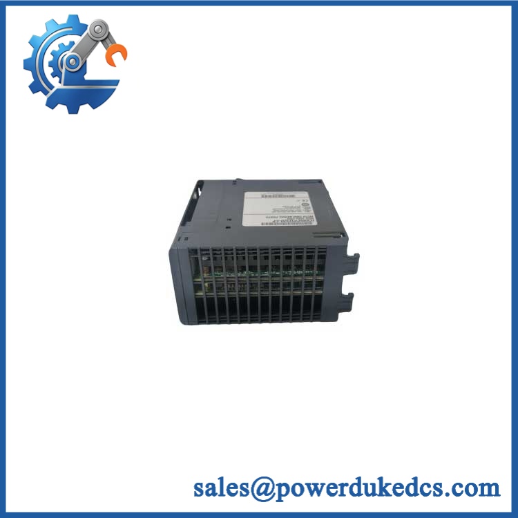
GE IC695PSD140A
Module 6: Quality Assurance SOP
Before shipment, each available GE IC695PSD140A should pass a documented laboratory-style inspection:
- OEM identification inspection — Verify GE/GE Fanuc markings, complete IC695PSD140A part number, revision information, serial/lot markings, and nameplate data.
- OEM anti-counterfeit visual inspection — Examine the housing, labels, terminal block, connector construction, PCB workmanship, and component markings for unauthorized modification or rework.
- Physical inspection — Check the housing, mounting mechanism, AC terminals, backplane connector, ventilation openings, and insulation surfaces for cracks, corrosion, contamination, or impact damage.
- Part-number verification — Confirm the physical unit against the requested IC695PSD140A specification before electrical testing.
- Controlled AC input test — Apply the specified AC input using an isolated, protected laboratory test source and verify normal startup behavior.
- Output-voltage verification — Measure the regulated output under appropriate test conditions and confirm that it remains within the manufacturer’s specified limits.
- Load test — Apply a controlled load within the rated operating range and monitor output stability, input current, and abnormal temperature rise.
- Backplane power verification — Where a compatible RX3i test rack is available, install the supply and verify that the rack receives the expected power.
- System startup verification — Confirm that compatible rack modules initialize normally without power-supply-related diagnostic faults.
- Thermal/stability test — Operate the supply under controlled load conditions and monitor for excessive heating, voltage drift, cycling, or intermittent shutdown.
- Final visual inspection — Recheck terminals, connectors, labels, mounting hardware, and enclosure condition after testing.
- Test record and packaging — Record the model number, revision, electrical test results, inspection date, and packaging condition before dispatch.
QA note: IC695PSD140A is a rack power supply, not a CPU or I/O controller. A generic RUN/ERR LED POST procedure should not be claimed as the primary acceptance test. Input-voltage verification, regulated-output measurement, controlled load testing, rack power verification, and thermal stability are the appropriate QA checkpoints.











 Start Chat


