

Description
- Model & Brand: GE Fanuc / General Electric IC697MDL654
- Series: Series 90-70 PLC
- Part Type: 48 VDC Positive/Negative Logic, 32-Point Discrete Input Module
- Physical Dimensions: Approximately 40.6 × 28.0 × 25.4 cm (W × H × D) for the installed module/terminal arrangement; verify the actual rack-mounted assembly before final cabinet drawings.
- Estimated Shipping Weight: Approximately 0.8–1.2 kg with protective packaging; use the actual packed weight for freight calculations.
- What’s in the Box: IC697MDL654 module, ESD protective packaging, and applicable inspection/QC documentation. The rack, backplane, and field terminal-board hardware are not assumed to be included.
Product Introduction
The GE IC697MDL654 is designed for the Series 90-70 PLC and occupies the VME-style backplane as a 32-point discrete DC input module. Four isolated groups of eight inputs allow separate field commons, while the positive/negative logic design accommodates sourcing and sinking field devices. This architecture is particularly useful in older process and power-generation cabinets where 48 VDC instrumentation remains in service.
At the field level, the module accepts -3 to +56 VDC, with a defined ON-state range of 33–56 VDC and OFF-state range of 0–10 VDC. All 32 points use the same selected input-filter timing—1 ms or 10 ms—rather than independent per-channel settings. That detail is easy to overlook when troubleshooting a replacement (the filter selection can change observed response time across the entire module).
Core Technical Specifications
| Parameter | Value |
|---|---|
| Manufacturer | GE Fanuc / General Electric |
| Model | IC697MDL654 |
| Series | Series 90-70 |
| Product Type | 48 VDC Positive/Negative Logic Discrete Input Module |
| Input Channels | 32 points |
| Channel Organization | 4 isolated groups × 8 inputs |
| Rated Input Voltage | 48 VDC |
| Input Voltage Range | -3 to +56 VDC |
| ON-State Voltage | 33–56 VDC |
| OFF-State Voltage | 0–10 VDC |
| Typical Input Current | 4.7 mA at rated voltage |
| Input Impedance | Approximately 9.12 kΩ typical |
| ON-State Current | Approximately 4–7 mA |
| OFF-State Current | 0–1.5 mA |
| Input Filter | 1 ms or 10 ms, module-wide selection |
| Group-to-Group Isolation | 500 V RMS |
| Input-to-Backplane Isolation | 1500 V RMS |
| Backplane Current | 0.30 A at 5 VDC |
| Approx. Backplane Power | Approximately 1.5 W |
| Interrupt Capability | Channel A1 edge-trigger interrupt support |
| Field Device Compatibility | 2-wire and 3-wire proximity switches, switches, pushbuttons, contacts |
| Logic Type | Positive/negative logic |
| Terminal Wiring | #22 to #14 AWG |
| Installation | Series 90-70 VME backplane |
| Mechanical Keying | Yes |
| Status Indication | Individual point LEDs |
| Firmware | Module configuration-dependent; no user application firmware |
| Hot Replacement | Do not assume live replacement |
| Lifecycle Position | Legacy / Obsolescence-Controlled |
Power and thermal considerations
The 0.30 A draw from the 5 VDC backplane represents approximately 1.5 W of nominal electrical power consumed by the module. Actual cabinet heat should be calculated from the complete rack power budget rather than treating the 1.5 W figure as a direct measured thermal output.
The module itself does not contain application memory or a processor comparable to a PLC CPU. Input configuration and point assignment are handled by the Series 90-70 control environment, while the physical module provides signal conditioning and isolation.
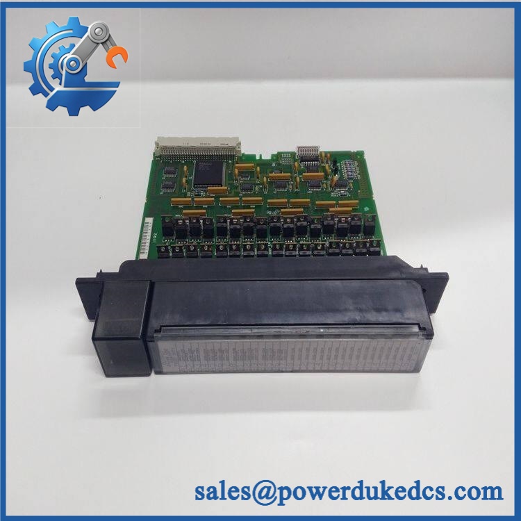
GE IC697MDL654
🚨 Global Compliance & Industry Certifications
The IC697MDL654 is legacy PLC I/O hardware, and compliance records should be maintained against the complete Series 90-70 installation, not inferred from the module label alone.
- UL/cUL: Series 90-70 equipment was produced for industrial-control applications under applicable North American requirements. Verify the exact hardware revision and system certification record.
- CE Mark: Verify the applicable historical GE/Series 90-70 declaration and installation requirements for the relevant production revision.
- ATEX / IECEx: Do not assume the standalone module has hazardous-area approval. Any Zone or Division-rated application requires the complete approved system arrangement.
- Marine approvals: DNV GL or other marine approval is not assumed for the standalone IC697MDL654.
- Electrical Isolation: The module provides 1500 V RMS input-to-backplane isolation and 500 V RMS group-to-group isolation; these are electrical specifications, not hazardous-area certificates.
- Country of Origin: Establish using manufacturing traceability or supplier documentation.
- HS classification: Confirm the final Harmonized System code with the destination-country customs broker.
For plant safety, isolation ratings matter because they reduce electrical interaction between field circuits and the PLC backplane. They do not, by themselves, authorize installation in a classified hazardous location.
Verify specific lot certifications with OEM.
🚨 Long-Term Storage & Asset Preservation Guide
Keep the in an ESD shielding bag until installation. Protect the rear backplane connector from dust and repeated handling, especially because oxidation on older connector surfaces can create intermittent input faults.
Use a clean, dry storage area without condensation. A practical warehouse target is below approximately 60% RH for long-duration inventory, even though the equipment may tolerate a broader non-condensing range during operation.
Before issuing the module, inspect the individual LED windows, card edge, mechanical key, front cover, and terminal interface for physical damage. Check for corrosion, discoloration, cracked components, or previous repair activity.
Record the module’s filter configuration requirement in the asset file. The 1 ms/10 ms selection applies to the module as a whole, so a replacement configured differently can change input-response behavior across all 32 channels.
Physical Installation Prerequisites
Install the only in the compatible GE Series 90-70 VME backplane and designated I/O slot. The module uses a mechanical keying system to prevent incorrect module types from being inserted into a keyed slot.
GE installation guidance calls for approximately 6 inches (152 mm) of clear space around the module for adequate ventilation. Preserve that original spacing rather than compressing adjacent wiring or adding equipment directly around the module.
Before insertion, verify the backplane connector, card guides, keying arrangement, and retaining hardware. The field terminal board should remain securely fastened to the rack, with the identification strap maintained so the wiring remains associated with the correct rack position.
Field wiring should use the specified #22 to #14 AWG range and remain arranged according to the original Series 90-70 wiring design. Check the field source carefully: this module is a 48 VDC input device, not a generic 24 VDC replacement.
GE installation instructions require the PLC to be powered down before module removal or installation. Do not treat the as a hot-swappable module.
Buyer’s FAQ — Logistics & Compliance Focus
Q: What HS Tariff Code should be used for ?
A: The module is a discrete PLC input component, but the final Harmonized System classification depends on the importing country’s tariff schedule and customs interpretation. Have the importer or customs broker confirm the code before the commercial invoice is finalized.
Q: Does Country of Origin follow the shipping location?
A: No. COO should be supported by the actual manufacturing or traceability documentation. The seller’s warehouse, export port, or fulfillment location does not by itself establish manufacturing origin.
Q: Does the come with the latest firmware pre-loaded?
A: This is not a standalone programmable controller. There is no user application firmware comparable to a Series 90-70 CPU. The module’s operating behavior is determined by its hardware configuration and the PLC’s I/O configuration, including the module-wide 1 ms or 10 ms input-filter setting.
Q: How should this module be insured and packed for shipment?
A: Insure it for the documented replacement value and photograph the full module, model label, mechanical key, connector, and packaging before dispatch. Use an ESD shielding bag, rigid protection around the backplane connector, moisture protection, and internal cushioning so the legacy module cannot shift within the carton during transport.











 Start Chat


