

Description
- Brand: GE / GE Fanuc
- Full Model Number: IC697MDL740
- Lifecycle Status: Legacy / Obsolete
- Core Function: High-current discrete DC output module
- Top 3 Technical Specs: 16 output points; 24/48 VDC rated output; 2 A maximum per point
- Output Logic: Positive logic / sourcing
- Output Groups: 4 groups of 4 points
- Group Current: 4 A maximum per group
- Operating Output Range: 20–60 VDC
- Inrush Capability: Up to 20 A for 20 ms
- Response Time: Approximately 2 ms ON / 2 ms OFF
- Backplane Isolation: 1500 VAC class
- Backplane Power: Approximately 0.15 A at 5 VDC
- System Family: GE Series 90-70
- Stock & Condition: New Surplus / Tested Surplus / Tested Refurbished subject to physical-unit confirmation
- Shipping: Emergency dispatch subject to confirmed stock and carrier cutoff
The GE IC697MDL740 is a 16-point discrete DC output module designed for the Series 90-70 PLC family. Its documented electrical class is 24/48 VDC positive-logic output, with a maximum of 2 A per output point and 4 A for each four-point group. The module operates across a 20–60 VDC output range and is intended for applications requiring higher-current DC switching than lower-rated Series 90-70 output modules.
The IC697MDL740 belongs to the legacy GE Series 90-70 I/O family. For maintenance teams supporting installed systems, the exact catalog number is important because similar Series 90-70 output modules can differ substantially in point count, voltage range, logic type, and current capacity.
Obsolescence & Supply Chain Deep Dive
A failed IC697MDL740 can interrupt field devices such as solenoids, relays, contactors, valves, and other DC loads even when the PLC CPU and the remainder of the rack continue operating normally. The module provides 16 discrete output points grouped into four groups of four, making both point-level current and group-level current important during replacement planning. An exact spare allows the maintenance team to restore the affected I/O position without converting the complete Series 90-70 platform.
From a TCO perspective, a board-level replacement can be considerably less disruptive than a full PLC migration when the installed control system remains serviceable. Existing logic, rack hardware, field wiring, documentation, and commissioning procedures can remain in place. Engineering effort is concentrated on verifying the replacement module, reproducing the original wiring, checking output polarity, and validating the connected loads (especially where several high-current loads share one output group).
Compatibility & Replacement Matrix
| Buyer Review Item | IC697MDL740 Assessment |
|---|---|
| Exact-Part Replacement | Drop-in Replacement for an existing IC697MDL740 installation, subject to wiring and electrical verification |
| PLC Platform | GE Series 90-70 |
| Module Type | Discrete DC output |
| Number of Outputs | 16 |
| Logic | Positive logic / sourcing |
| Rated Output Voltage | 24/48 VDC |
| Operating Output Range | 20–60 VDC |
| Maximum Current | 2 A per point |
| Maximum Group Current | 4 A per group |
| Output Grouping | 4 groups × 4 points |
| Inrush Capability | Up to 20 A for 20 ms |
| Response Time | Approximately 2 ms ON / 2 ms OFF |
| Firmware Flash | No routine firmware-flash requirement |
| Hardware Modification | Normally not required for an exact-model replacement |
| Configuration Work | Required verification of output wiring, polarity, field supply, and load assignment |
| Installation Labor | Approximately 1–3 hours as a planning allowance |
| Functional Verification | Approximately 2–4 hours depending on field-device access |
| Cross-Model Replacement | Engineering verification required before substituting another Series 90-70 output module |
The should not be confused with lower-current Series 90-70 output modules. A substitute with fewer points or lower current capacity may fit the same general PLC family but still be unsuitable for the installed field loads.
Field Traps to Watch Out For
Output-current mismatch: The is rated for up to 2 A per output point. Confirm the actual steady-state and inrush current of every connected field device before approving a substitute.
Group-current overload: The four outputs within a group share a 4 A maximum group rating. Four individually acceptable loads can still exceed the group limit when energized together. Calculate both point current and combined group current.
Positive-logic wiring: The module uses positive-logic or sourcing output operation. Verify the load wiring and return path before energizing the replacement. A sink/source mismatch can prevent the field device from operating correctly.
Supply-voltage verification: Confirm that the field supply remains within the documented 20–60 VDC operating range and matches the connected equipment requirements.
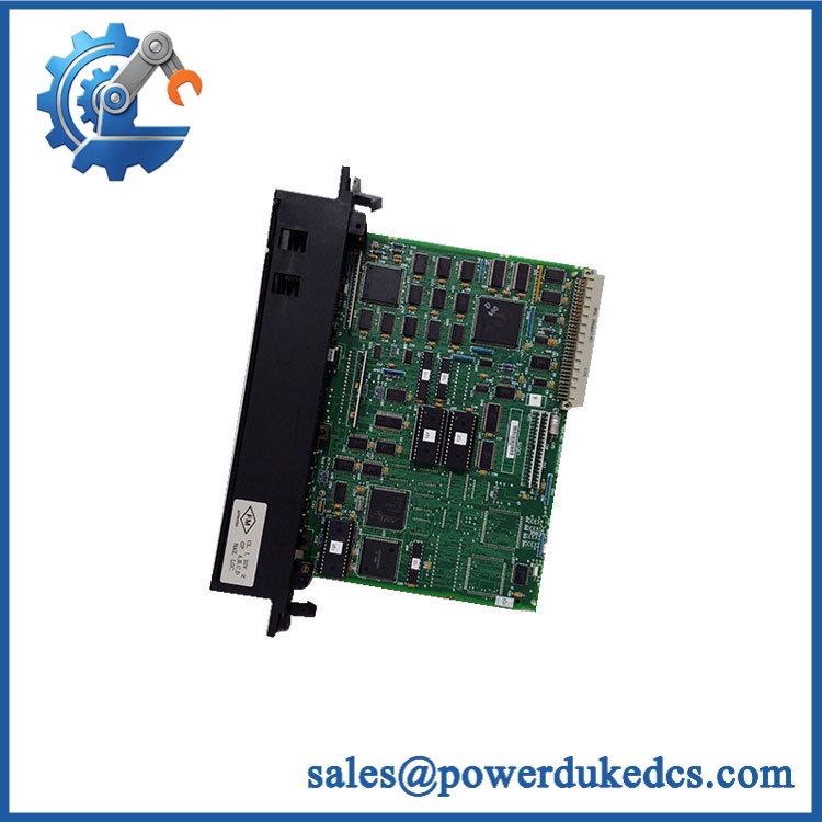
GE IC697MDL740
Quality Assurance & Testing SOP
Part-number verification: Confirm the physical module marking as . Record manufacturer identification, hardware revision, serial number, and all visible catalog information before testing.
OEM anti-counterfeit visual inspection: Compare housing construction, labels, PCB layout, terminal arrangement, component population, connector geometry, and identification markings against the approved GE reference. Any inconsistent labeling or unexplained board modification triggers manual review.
Mechanical inspection: Examine the enclosure, mounting hardware, terminal interface, PCB, and connector areas for cracking, deformation, corrosion, contamination, loose parts, and signs of thermal stress.
Terminal inspection: Check all field terminals for oxidation, bent contacts, damaged clamps, loose hardware, and evidence of arcing or excessive load current.
Configuration capture: Photograph the installed module and record every field connection before removal. Preserve the original point-to-device mapping for the replacement installation.
Power-on self-test (POST): Install the module in an approved Series 90-70 test rack and apply controlled power. Verify module initialization and available diagnostic indications before applying external loads.
Output-channel testing: Exercise all 16 output points individually. Verify correct ON/OFF switching and stable operation at the required DC test voltage. Record the result for every channel.
Output load testing: Apply representative resistive and approved simulated inductive loads. Monitor switching stability, output voltage behavior, current handling, and thermal response.
Current-load verification: Test representative output points at controlled current levels below the 2 A point rating. Separately monitor four-point groups to confirm that combined loading remains within the 4 A group limit.
Inrush testing: Where the test fixture supports it, simulate representative startup or inrush conditions and verify stable output behavior within the documented 20 A for 20 ms capability.
Response-time verification: Measure representative ON and OFF transitions with a calibrated oscilloscope or equivalent test instrument. Compare measured behavior with the approximately 2 ms ON and 2 ms OFF specification.
Isolation testing: Where the laboratory environment and safety procedure permit, perform an approved isolation test appropriate to the module’s backplane isolation rating.
Thermal observation: Operate representative loads for a controlled period and monitor the module for abnormal temperature rise, unstable outputs, or signs of excessive dissipation.
Final QA release: Record exact model, revision, serial number where available, 16-channel test results, representative load current, group loading, response-time results, isolation-test result where performed, technician, and test date. Approved units are handled using ESD protection and protective packaging.
Procurement & Lifecycle FAQ
Is the genuinely in stock and what is the cutoff for emergency shipping?
Physical availability should be confirmed against the actual unit before the PO is released. For emergency procurement, confirm quantity, exact catalog number, condition, revision, warehouse location, destination, and carrier cutoff before payment.
How do you verify the condition and authenticity of an obsolete ?
The inspection should include exact model verification, revision and label inspection, PCB and terminal examination, controlled Series 90-70 power-up, all-16-point switching tests, and representative load testing. Commercial condition should be stated clearly as New Surplus, Tested Surplus, or Tested Refurbished.
Are there any firmware compatibility issues I should warn my engineers about before issuing the PO?
No routine firmware-flash requirement applies to the module as a discrete output device. The more important checks are output polarity, field-supply voltage, maximum point current, group current, and compatibility with the actual connected loads.
Is the a direct replacement for an installed unit?
An exact replacement can generally be treated as a drop-in replacement in the corresponding Series 90-70 application without planned hardware modification. Engineers should still verify terminal wiring, sourcing polarity, supply voltage, individual load current, and four-point group loading before returning the rack to service.
What warranty and return terms should procurement require?
The PO should specify the exact catalog number, hardware revision where applicable, condition classification, test status, warranty duration, DOA definition, return period, and return-freight responsibility. For legacy PLC hardware, retain the actual-unit identification record and pre-shipment test report with the procurement documentation.











 Start Chat


