

Description
- Brand: GE
- Full Model Number: IC800SS1228R02-CE
- System / Series Family: SNAP I/O / SNAP PAC safety I/O
- Core Function: Safety relay I/O module for emergency-stop and safety-interlock circuits
- Top 3 Hardcore Specs: 12 safety inputs / 8 safety outputs / Dual-channel safety circuit architecture
- Module Type: Safety Relay Module
- Input Channels: 12
- Output Channels: 8
- Safety Function: Emergency shutdown and safety interlocking
- Stock Status: New Surplus / Factory Sealed — exact physical condition to be confirmed before quotation
Module 3: Technical Product Introduction
A safety I/O failure has a different maintenance consequence from an ordinary control I/O fault: the machine may be forced into a safe state, stopping production until the safety circuit is restored. The IC800SS1228R02-CE is identified in available technical references as a safety relay module associated with the SNAP I/O architecture. The listed configuration provides 12 safety inputs and 8 safety outputs, with dual-channel circuitry intended for emergency-stop and safety-interlock applications.
For replacement work, the safety function is the critical point. This is not simply a conventional digital I/O module that can be exchanged according to channel count. The safety logic, input wiring, output architecture, controller configuration, and required machine safety validation all have to correspond to the original installation. Available references also associate the module with SNAP PAC control and configuration software, but the exact controller and firmware combination should be confirmed from the customer’s installed system before substitution.
Module 4: Application Scenarios & Field Realities
- At machine emergency-stop stations, the module can be used to monitor safety devices and control the associated safety outputs. The wiring should be checked against the approved safety circuit drawing rather than copied solely from terminal position.
- For automated production equipment, dual-channel safety circuits are relevant to interlocks on conveyors, assembly equipment, machine guards, and other hazardous motion. A channel fault or discrepancy may intentionally prevent the equipment from returning to the run state.
- On robotic workstations, safety inputs can be associated with gate switches, emergency-stop devices, and other protective devices. After replacement, functional testing must cover the complete safety chain, including the final controlled device—not just the module LEDs.
- During a plant shutdown, replacement time is often limited by validation rather than physical installation. Record the existing module identification, controller model, wiring arrangement, and safety configuration before removing the failed unit. A visually identical module does not by itself prove safety-system equivalence.
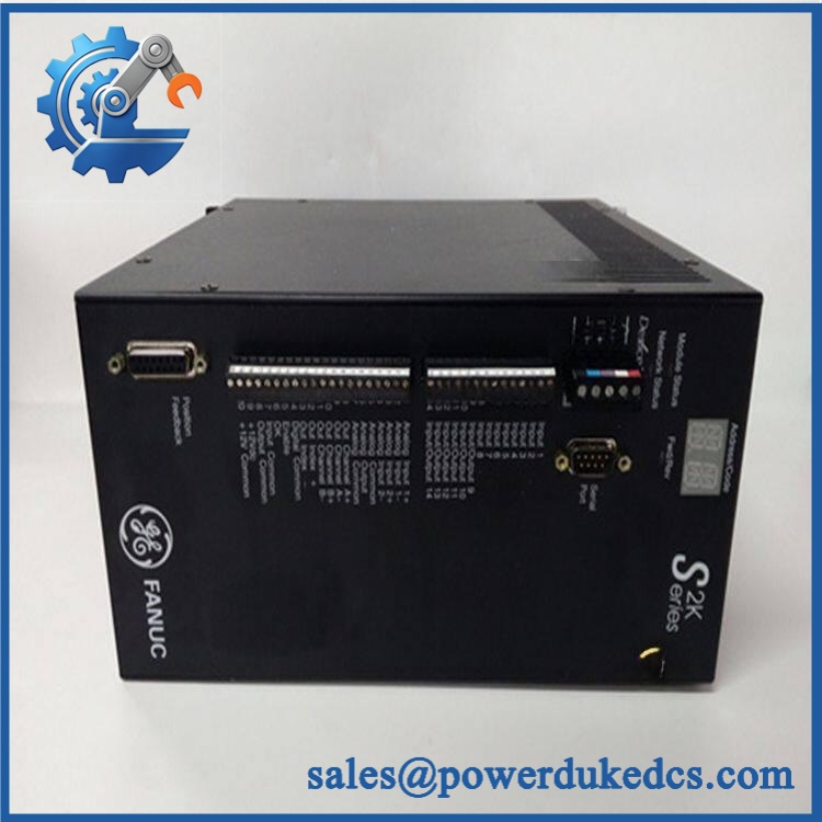
GE IC800SS1228R02-CE
Module 5: Migration, Compatibility & Installation Traps
Replacement Matrix
| Replacement Case | Classification | Engineering Requirement |
|---|---|---|
| IC800SS1228R02-CE replacing the identical IC800SS1228R02-CE | Drop-in Replacement | Verify exact part number, controller compatibility, wiring, and approved safety configuration |
| Same module family with a different hardware revision | Software Compatible — Verify First | Confirm firmware, configuration, safety parameters, and certification requirements |
| Conventional digital I/O module replacing the safety relay module | Hardware Modification Required | Redesign the safety circuit and complete the required safety validation |
| Different safety I/O architecture | Hardware Modification Required | Review safety category, wiring, diagnostics, output behavior, and controller integration |
Field Traps — Watch Out
Safety configuration mismatch: Do not commission the replacement simply because all 20 I/O channels appear functional. Safety-related inputs and outputs must correspond to the approved machine safety design. Available references describe the module as having 12 safety inputs and 8 safety outputs with dual-channel safety circuitry.
Controller and software verification: Available references associate this module with SNAP PAC systems and PAC Control / PAC Project software. Before replacement, confirm the installed controller, configuration version, and applicable firmware. Do not assume that a later or visually similar module will automatically load the existing safety configuration.
Output-device verification: Check what each safety output actually controls. Contactors, motor starters, valves, drives, and other final elements have different electrical requirements. The replacement module should not be energized into an unknown load arrangement.
Safety validation after replacement: A successful power-up is not a complete acceptance test. Emergency-stop circuits, guard interlocks, dual-channel behavior, reset logic, fault response, and the final controlled equipment should all be functionally checked according to the site’s approved safety procedure.
Module 6: Quality Assurance SOP
The pre-shipment inspection for an IC800SS1228R02-CE should follow a controlled safety-module inspection sequence:
- Part-number verification — Confirm the physical identification against IC800SS1228R02-CE and record all visible markings, revision information, and traceability identifiers.
- OEM anti-counterfeit visual inspection — Examine the housing, labels, PCB markings, connector construction, terminal identification, and manufacturing marks for inconsistent printing, alteration, or unauthorized rework.
- Mechanical inspection — Check the enclosure, connectors, mounting points, terminal interfaces, and accessible PCB areas for cracks, contamination, corrosion, deformation, or impact damage.
- Power-on self-test (POST) — Where an approved test fixture is available, energize the module under controlled conditions and check applicable power, status, and fault indicators.
- Safety-input verification — Test representative input channels using an approved test configuration. Verify expected response to normal and fault conditions without bypassing the intended safety architecture.
- Safety-output verification — Confirm the applicable output channels change state according to the approved test procedure. Check abnormal or fault-state behavior where the test fixture supports it.
- Communication handshake verification — Where a compatible SNAP PAC test environment is available, verify that the controller recognizes the module and that the configured I/O data is exchanged correctly.
- Safety-function verification — Confirm the module’s response within the applicable safety test circuit, including emergency-stop and interlock conditions. This test must not be represented as a machine safety certification unless the complete installed system has been evaluated.
- Final inspection and packaging — Photograph the exact part-number label, record the test results, protect connectors and exposed interfaces, apply appropriate ESD precautions, and package the unit against mechanical shock and moisture.
The acceptance record should connect the identification, visual inspection, electrical screening, I/O verification, and packing record to the unit shipped. Because this is a safety-related component, replacement suitability must ultimately be confirmed against the customer’s complete safety architecture rather than by part-number similarity alone.











 Start Chat


