

Description
- Brand: GE
- Full Model Number: IS200AEADH4A
- OEM Part Number: 109W3660P001
- System/Series Family: EX2100 Excitation Control
- Core Function: Alternative Energy Application D interface board for excitation-control applications
- Top 3 Hardcore Specs: 6 channels; 1–5 VDC input span; 24 VDC outputs
- Board Type: Alternative Energy Application D
- Analog Output: 0–20 mA
- Technology: Surface-mount
- Manual Reference: GEH-6777
- Stock Status: New Surplus / Factory-Sealed or Fully Tested Refurbished subject to actual inventory condition
Available technical records identify IS200AEADH4A as a GE Alternative Energy Application D board associated with the EX2100 Series, with six channels, a 1–5 VDC input span, 24 V outputs, and 0–20 mA analog output capability. The reference 109W3660P001 is also associated with this exact model in equipment records.
Module 3: Technical Product Introduction
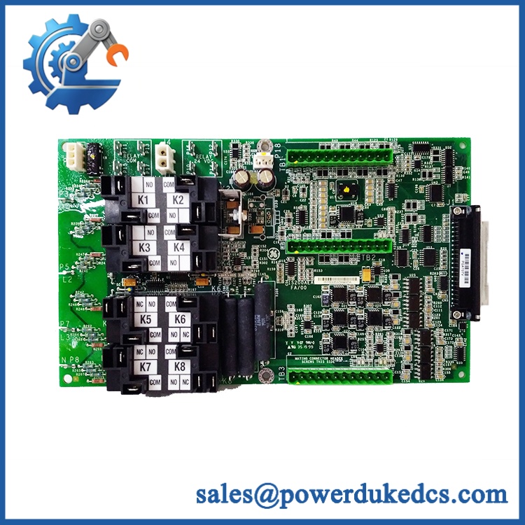
In an excitation-control cabinet, an incorrect analog signal can be just as disruptive as a failed power component. The GE IS200AEADH4A, part number 109W3660P001, is identified as an Alternative Energy Application D board used in GE’s EX2100 excitation-control architecture. Available technical documentation records describe a six-channel configuration with a 1–5 VDC input span, 24 VDC outputs, and 0–20 mA analog output capability.
The exact board identity should be preserved during replacement. The IS200AEADH4A is not simply a generic analog I/O card; its function is tied to the EX2100 application architecture. Some third-party listings incorrectly describe the same part number as a generic 16-channel analog input module, with specifications such as RTD and thermocouple inputs. Those claims conflict with the more specific EX2100 documentation identifying the board as Alternative Energy Application D, so those unsupported specifications should not be used for a technical PDP.
GE IS200AEADH4A 109W3660P001
Module 4: Application Scenarios & Field Realities
- Within an EX2100 excitation system, the IS200AEADH4A can interface application-specific analog signals with the excitation-control architecture. When a measured value suddenly shifts outside its expected range, verify the field transmitter, wiring, reference voltage, and board input before replacing the PCB.
- For generator excitation troubleshooting, the reported 1–5 VDC input span is particularly important. A signal outside the configured range should not automatically be diagnosed as a failed AEAD board; first confirm the source signal with an independent calibrated meter.
- Where analog output is used for downstream control equipment, the documented 0–20 mA output requires correct loop wiring and load conditions. A healthy board can still appear faulty if the loop is open or incorrectly terminated.
- During spare-board replacement, retain both identifiers: IS200AEADH4A and 109W3660P001. The complete identification provides a much safer basis for matching the replacement than the generic description “AEAD board.”
Module 5: Migration, Compatibility & Installation Traps
Replacement Matrix
| Replacement Case | Classification | Engineering Requirement |
|---|---|---|
| 109W3660P001 → identical assembly | Drop-in Replacement | Verify complete part number, revision, connectors, and configuration |
| Same hardware with documented compatible revision | Software Compatible | Confirm application configuration and controller compatibility |
| Different AEAD/Alternative Energy board | Hardware Modification Required | Validate channels, signal ranges, outputs, wiring, and application |
| Generic analog input module | Hardware Modification Required | Not interchangeable without engineering validation |
Field Traps — Watch Out
1. Do not use generic analog-I/O specifications for this board.
Search results contain conflicting descriptions of the . One listing calls it a 16-channel analog input module, while a more specific equipment record identifies it as Alternative Energy Application D, six channels, 1–5 VDC input, 24 V outputs, and 0–20 mA analog output. For procurement and technical documentation, the latter configuration is the safer identification basis unless the applicable GE manual confirms otherwise.
2. Verify the 109W3660P001 cross-reference.
The exact combination appears in equipment records as a power-conversion/application board reference. Preserve both numbers when ordering to reduce the chance of receiving a visually similar board.
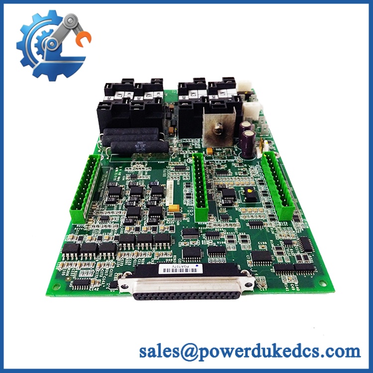
Installation note: De-energize and discharge the applicable excitation equipment before removing the board. Record every connector position and board-revision marking. For analog circuits, verify polarity and signal range before reconnecting field wiring.
GE IS200AEADH4A 109W3660P001
Module 6: Quality Assurance SOP
For , QA should focus on exact identification, analog signal integrity, and application compatibility.
- Part-number verification: Confirm and 109W3660P001 from the physical board markings.
- OEM anti-counterfeit visual inspection: Examine GE identification, PCB markings, revision code, connectors, component layout, labels, and manufacturing information.
- Revision verification: Record the complete revision designation shown on the PCB.
- Mechanical inspection: Check PCB edges, connectors, mounting points, terminal interfaces, and board hardware.
- Component inspection: Look for overheating, cracked components, corrosion, damaged connectors, contamination, or evidence of unauthorized repair.
- Power-on self-test (POST): Install the board in an approved test environment and verify normal initialization.
- Supply verification: Confirm the applicable board supply rails before applying functional test signals.
- Analog-input verification: Apply calibrated signals across the documented 1–5 VDC input span and verify the expected response.
- Channel verification: Test each of the documented six channels independently.
- 24 V output verification: Confirm the applicable 24 VDC outputs under controlled test conditions.
- Analog-output verification: Exercise the 0–20 mA output path and compare the measured loop current against the commanded value.
- Signal-isolation check: Verify the applicable input/output isolation and grounding arrangement against the approved documentation rather than assuming a generic isolation rating.
- Diagnostic verification: Check the host system for board, signal, configuration, or application faults.
- Communication handshake verification: Verify correct interaction with the associated control hardware where applicable.
- Final inspection: Recheck connectors, labels, revision markings, PCB condition, and packaging.
- Traceability: Record model number, OEM part number, revision, serial/manufacturing information where available, test equipment, applied input values, measured outputs, test results, inspection date, and condition classification.
Procurement note: Use the complete description GE — 109W3660P001 — Alternative Energy Application D — . Because online listings contain materially conflicting specifications for this part, publishing unverified claims such as “16-channel RTD/thermocouple input” would create a compatibility risk. The available -specific record supports the six-channel, 1–5 VDC, 24 VDC output, and 0–20 mA configuration instead.











 Start Chat


