

Description
- Brand: GE
- Full Model Number: IS200AEPAH1AHD
- System/Series Family: Speedtronic Mark VI / Alternative Energy
- One-Sentence Core Function: Alternative Energy Pitch Axis board used within GE turbine and wind-energy control architectures
- Top 3 Hardcore Specs: AEPA functional designation; 7 onboard fuses; 4 transformers
- Board Type: Printed circuit board assembly
- Functional Acronym: AEPA
- Primary Application: Pitch-axis control / alternative-energy turbine systems
- Protection Components: Metal-oxide varistors and onboard fusing
- Revision Identification: H1A base hardware with HD assembly/revision suffix
- Stock Status: New Surplus / Fully Tested Refurbished subject to availability
Module 3: Commercial-Technical Deep Dive
A failed IS200AEPAH1AHD should not be treated as a generic Mark VI replacement board. The AEPA designation identifies the Alternative Energy Pitch Axis function, and available GE board references associate the IS200AEPAH1A family particularly with wind-turbine applications. The board is part of the Mark VI control hardware family and contains the circuitry required for pitch-axis control interfaces. Available technical references for the IS200AEPAH1A family identify multiple I/O functions, including analog inputs, encoder inputs, analog output, discrete inputs, relay outputs, RS-485 interfaces, and a brake-control output.
Physical construction is also important during replacement. The IS200AEPAH1A family uses an auxiliary-board arrangement, with the auxiliary assembly mechanically secured to the main PCB through standoffs and connected through board-level pin interfaces. Available hardware references identify seven onboard fuses and four transformers on the IS200AEPAH1AHD assembly, making this more than a simple passive termination board. Those components should be inspected individually during incoming QC, especially on units removed from service after a drive, brake, or field-power fault. The exact HD suffix should be matched from the physical nameplate because related IS200AEPAH1A assemblies exist with different final suffixes.
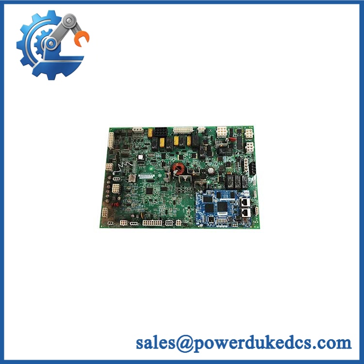
GE IS200AEPAH1AHD
Module 4: Compatibility & Installation Traps
Migration/Compatibility
- System Role: Alternative Energy Pitch Axis PCB for GE turbine/wind control applications.
- Base Assembly: IS200AEPAH1A.
- Requested Assembly: IS200AEPAH1AHD.
- Functional Acronym: AEPA.
- Architecture: Main PCB with an optional/attached auxiliary board arrangement on applicable configurations.
- Replacement Type: Same-part-number replacement is preferred; do not substitute a visually similar Mark VI board based only on connector geometry.
- Configuration: Verify the installed pitch-control wiring, encoder arrangement, relay circuits, and associated controller configuration before commissioning.
- Logic Rewrite: A like-for-like board replacement normally does not imply a control-logic rewrite, but application-specific calibration, configuration, and feedback checks may be required.
- Revision Matching: Match the complete IS200AEPAH1AHD identifier and assembly marking. Related IS200AEPAH1A variants include different suffixes and should not be assumed interchangeable.
⚠️ Field Traps (Watch Out)
1. Do not bypass the onboard protection devices during troubleshooting.
The IS200AEPAH1AHD family is documented with seven fuses and multiple transformers. A blown fuse may be the consequence of a downstream fault rather than the primary failure. Replacing the fuse without finding the initiating fault can damage the replacement board.
2. Verify encoder and pitch-feedback wiring before applying field power.
The AEPA family is associated with encoder, analog, discrete, relay, and brake-control functions. A wiring error on a feedback or brake circuit can produce misleading control diagnostics even when the PCB itself passes a bench inspection.
3. Confirm auxiliary-board configuration.
The IS200AEPAH1A family can include an attached auxiliary board secured through standoffs and board-to-board connectors. Verify that the replacement has the same auxiliary assembly arrangement as the removed unit before installation.
Module 5: Quality Assurance SOP
Each available GE IS200AEPAH1AHD should undergo a documented board-level inspection before shipment:
- OEM anti-counterfeit visual inspection: Verify GE markings, complete catalog number, assembly suffix, PCB layout, connector positions, component population, and board labeling.
- Revision verification: Confirm the physical identification reads IS200AEPAH1AHD and record all additional readable board numbers.
- PCB condition inspection: Examine the board for corrosion, contamination, cracked components, lifted components, burned areas, damaged connectors, and prior repair evidence.
- Fuse inspection: Check all seven onboard fuses for correct physical condition, visible damage, discoloration, or incorrect replacement types.
- Transformer inspection: Inspect all four transformers for cracked cases, physical displacement, overheating indicators, and damaged solder joints.
- MOV inspection: Check surge-suppression components for cracking, discoloration, or evidence of a previous transient event.
- Auxiliary-board inspection: Verify standoffs, mounting screws, board-to-board connectors, and auxiliary PCB condition.
- Power-on self-test (POST): Install the board in an approved Mark VI test fixture where applicable and verify expected supply, board-status, and diagnostic behavior.
- I/O verification: Test the available analog, discrete, relay, encoder, RS-485, and brake-related circuits using a controlled fixture appropriate to the installed board configuration.
- Communication handshake verification: Where the test rack supports the associated control interface, verify communication between the AEPA assembly and its host controller.
- Feedback simulation: Apply controlled encoder or simulated feedback signals and confirm the expected input response without connecting production machinery.
- Protection review: Confirm that fuse and surge-protection circuitry remains intact after controlled testing.
- Final QC record: Document catalog number, exact suffix, assembly revision, fuse condition, auxiliary-board configuration, functional test results, and technician sign-off.
- ESD-safe packaging: Package the tested PCB in ESD-protective material with rigid support around connectors and exposed components.
The available documentation is especially useful for physical inspection: the AEPAH1A family is reported with two LED indicators, numerous edge connectors, auxiliary-board mounting hardware, and multiple protection components. A proper receiving inspection should therefore compare the complete physical assembly—not merely the top-level catalog number—to the requested IS200AEPAH1AHD.
Module 6: CRO-Driven Buyer FAQ
What is the GE IS200AEPAH1AHD used for?
The IS200AEPAH1AHD belongs to the GE AEPA, or Alternative Energy Pitch Axis, hardware family. References associate the IS200AEPAH1A series with GE Mark VIe wind-turbine applications, while the requested HD assembly is also documented within GE Mark VI board references. The exact installed application should be confirmed from the equipment bill of materials and board identification before substitution.
Is IS200AEPAH1AHD the same as IS200AEPAH1A?
The base board designation is IS200AEPAH1A, while IS200AEPAH1AHD identifies a specific assembly/revision combination. Related variants such as IS200AEPAH1AAA, IS200AEPAH1AFD, and IS200AEPAH1ABB are also commercially documented. Do not assume the final suffix can be ignored during procurement.
Can the IS200AEPAH1AHD be hot-swapped?
Do not treat this board as a universal hot-swap component. The safe removal and installation method depends on the installed Mark VI architecture, cabinet power arrangement, and plant maintenance procedure. Isolate the applicable energy sources and follow the site’s approved turbine-control maintenance procedure before handling the board.
What should I verify before ordering this exact board?
Confirm the complete IS200AEPAH1AHD identifier, the installed Mark VI or related alternative-energy platform, auxiliary-board arrangement, connector layout, encoder and brake wiring, and the field power configuration. A photo of the existing board’s complete nameplate is useful because several IS200AEPAH1A variants exist.
What warranty and technical support should I expect?
Warranty duration should be stated against the exact unit condition and test status on the quotation. Technical support should cover part-number verification, assembly/revision matching, connector and I/O compatibility, installation guidance, and documented bench-test results. Turbine application engineering, pitch-control tuning, or production commissioning should not be represented as included unless explicitly contracted.











 Start Chat


