

Description
- Brand: GE General Electric
- Full Model Number: IS200DTAIH1ABB
- Lifecycle Status: Legacy / Obsolete Support
- Core Function: Simplex analog input/output terminal board for GE Mark VI
- Top 3 Technical Specs: 10 analog inputs; 2 analog outputs; 37-pin JR1 connector + 48-position TB1 terminal strip
- Stock & Condition: New Surplus / Tested Refurbished; Physical stock confirmation required; Emergency dispatch subject to cutoff
The IS200DTAIH1ABB is identified as a Simplex Analog Input/Output Terminal Board in the GE Mark VI Speedtronic platform. Published technical data specifies 10 analog inputs, 2 analog outputs, a 37-pin JR1 connector, and a 48-screw TB1 terminal block.
Module 3: Obsolescence & Supply Chain Deep Dive
A failed GE Mark VI terminal board can leave an otherwise serviceable turbine-control system unable to receive or transmit critical analog signals. The IS200DTAIH1ABB provides the field termination and signal-interface point for a simplex analog I/O configuration, with 10 analog inputs and 2 analog outputs. The board mounts in a plastic holder designed for DIN-rail installation, while its TB1 terminal strip provides 48 screw connections. For a legacy installation, obtaining the exact board can be considerably less disruptive than redesigning field wiring around a different interface.
The TCO advantage is strongest when the failure is localized. A matching terminal board can preserve existing field cabling, panel architecture, signal assignments, and Mark VI engineering, avoiding the labor associated with cabinet changes and broader controls migration. One output can also be configured differently through jumper settings, so replacing the board with the wrong configuration can create commissioning risk even when the PCB appears physically identical.
Module 4: Compatibility & Replacement Matrix
| Purchase Approval Item | Assessment |
|---|---|
| Replacement Classification | Conditional Drop-in Replacement |
| System Family | GE Mark VI Speedtronic |
| Software Compatibility | No standalone firmware flash normally expected; verify Mark VI I/O configuration |
| Hardware Modification | Normally not required for an exact same-model replacement |
| Estimated Physical Changeover | 1–3 hours |
| Commissioning / Validation | Additional time for signal checkout and jumper verification |
| Cost Exposure | Typically much lower than replacing the associated control architecture |
Field Traps — Watch Out
- Jumper configuration: The board contains numerous jumpers used to configure current and voltage functions. Published documentation specifically notes that one analog output can be configured for a different current range through jumper changes. Photograph and record the original jumper positions before removal.
- Terminal wiring mismatch: TB1 has 48 screw connections, while JR1 is a 37-pin connector. Verify every field termination against the installed wiring documentation before energizing the replacement. The ground/SCOM connection also requires careful attention.
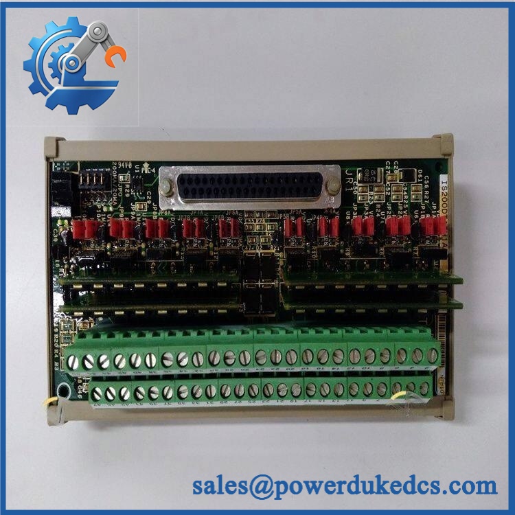
GE IS200DTAIH1ABB
Module 5: Quality Assurance & Testing SOP
The replacement should be processed as controlled turbine-control inventory with documented evidence of inspection and testing.
- Incoming traceability: Record GE markings, complete IS200DTAIH1ABB part number, revision, serial information, and available date-code details.
- OEM anti-counterfeit visual inspection: Check PCB markings, labels, component population, connector construction, solder quality, terminal-block condition, and evidence of unauthorized repair.
- Mechanical inspection: Verify the PCB, DIN-rail mounting holder, mounting hardware, JR1 connector, TB1 terminal strip, and board surfaces.
- Power-on self-test (POST): Apply controlled test power and verify expected startup behavior and applicable diagnostic indications.
- Electrical verification: Check supply paths, grounding continuity, fuse condition where applicable, and abnormal current draw.
- Analog input testing: Simulate representative voltage/current signals across the applicable input channels and verify correct acquisition.
- Analog output testing: Exercise both output channels and verify expected current response and configuration-dependent ranges.
- Jumper verification: Compare every installed jumper position with the documented reference configuration before functional testing.
- Signal isolation / continuity checks: Verify applicable field-to-board paths and connector continuity.
- Extended operation: Run representative analog signals continuously while monitoring stability, temperature, and intermittent faults.
- Final QC release: Record part number, revision, jumper configuration, test results, inspection date, and technician approval.
Module 6: Procurement & Lifecycle FAQ
1. Is the GE IS200DTAIH1ABB genuinely in stock, and what is the cutoff for emergency shipping?
Physical availability should be confirmed against the exact IS200DTAIH1ABB revision before PO release. Some independent listings currently show this model as available, but emergency procurement should be based on a physical stock check, current photographs, and exact part-number confirmation rather than a catalog status. Same-day dispatch depends on order approval, payment clearance, warehouse cutoff, and carrier collection.
2. How do you guarantee the condition and authenticity of this obsolete GE terminal board?
Verification should combine physical identification with functional testing. Inspect the GE markings, PCB construction, connectors, terminal strip, components, and jumper configuration before conducting controlled electrical and analog signal tests. Retain serial/part-number photographs and test records with the procurement file.
3. Are there firmware compatibility issues engineers should check before issuing the PO?
This board is primarily a terminal/interface board, so the main risks are hardware configuration and signal compatibility rather than a conventional firmware upgrade. Engineers should confirm the installed Mark VI I/O architecture, field signal types, wiring, and jumper positions before approval.
4. Can the replace a failed board without cabinet modification?
An exact same-model replacement is generally intended to retain the existing mounting and field wiring arrangement. The board is designed for DIN-rail mounting through its plastic holder. Before installation, confirm TB1 wiring, JR1 connections, jumper settings, and the physical mounting arrangement against the failed unit.
5. What warranty and return terms should procurement require?
Specify , exact revision, condition, testing status, warranty period, and return procedure in the PO. Warranty coverage should address DOA and verified functional defects, while excluding damage caused by incorrect field wiring, improper jumper settings, electrical overstress, or installation-related faults.











 Start Chat


