

Description
- Brand: GE
- Full Model Number: IS200EGDMH1ADF
- Lifecycle Status: Legacy / Obsolescence-Risk
- Core Function: Exciter field ground detection and leakage-current monitoring
- Top 3 Technical Specs: EX2100 excitation platform; field-ground detection; simplex or redundant 1/3-board architecture
- Stock & Condition: New surplus / tested refurbished — verify EPBP backplane, P2 configuration, and excitation-system revision before PO
The IS200EGDMH1ADF is identified in available technical references as a GE Exciter Ground Detection Module used with the EX2100 excitation system. It works with a test board to detect ground leakage in the exciter field circuit; simplex systems use one module, while redundant arrangements use three.
Module 3: Obsolescence & Supply Chain Deep Dive
A failed IS200EGDMH1ADF can remove field-ground fault detection from an excitation system even when the generator, regulator, and other control electronics remain operational. This module monitors leakage associated with the exciter field circuit and can detect ground conditions from both the AC and DC sides of the field circuit. In a simplex configuration, one board is used; redundant systems can use three boards configured as Controller, Master 1, and Master 2.
From a TCO standpoint, replacing the failed detector can preserve the existing excitation cabinet, test-board arrangement, field wiring, and protection philosophy. That is generally much less expensive than redesigning the excitation system around a different ground-detection architecture. The procurement risk is configuration-specific. The board uses P1 and P2 backplane connectors, and the redundant-role configuration is controlled through P2-related settings, so the exact installed architecture must be documented before replacement.
Module 4: Compatibility & Replacement Matrix
| Procurement Check | IS200EGDMH1ADF Assessment | Engineering Action |
|---|---|---|
| Replacement Type | Drop-in Replacement for a matching GE exciter ground-detection installation | Verify complete board number, revision, and system configuration |
| Software Compatibility | Configuration-dependent | Verify EX2100 application, diagnostics, and redundant-role configuration |
| Hardware Modification | Normally none for an exact board match | Confirm EPBP backplane, P1/P2 connectors, and test-board arrangement |
| Typical Switch Time | Approx. 2–4 hours | Allow additional time for ground-detection functional checks |
| Estimated Engineering / Testing Cost | Approx. 500–2,000 | Include field-ground simulation and system diagnostic testing |
| Alternative | Excitation ground-detection redesign | Requires engineering, wiring, and protection review |
Field Traps — Watch Out
Simplex versus redundant configuration: One IS200EGDMH1ADF is used in a simplex system, while a redundant system can use three boards with Controller, Master 1, and Master 2 roles. The replacement must preserve the installed architecture rather than simply replacing one physical PCB.
P2 configuration: Available technical documentation states that redundant-board roles are controlled through pins on the P2 connector. Record the installed P2 configuration before removing the failed board and reproduce it on the replacement.
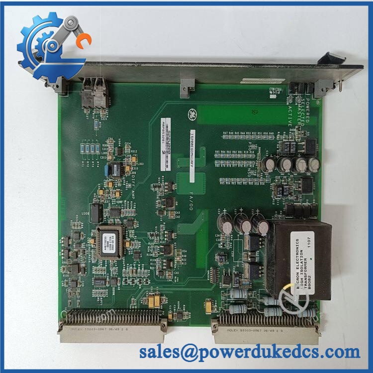
GE IS200EGDMH1ADF
Module 5: Quality Assurance & Testing SOP
The IS200EGDMH1ADF should receive controlled inspection and excitation-system functional testing before shipment.
1. Incoming inspection
- Record manufacturer, complete part number, serial/date code, and revision markings.
- Perform OEM anti-counterfeit visual inspection.
- Inspect PCB surfaces, P1/P2 connectors, front panel, relays, capacitors, and mounting hardware.
- Check for corrosion, contamination, cracked components, heat damage, damaged connector pins, or unauthorized rework.
2. Configuration verification
- Confirm identification.
- Record hardware and artwork revisions.
- Verify the board is configured for the applicable simplex or redundant architecture.
- Document P2-related configuration settings.
- Confirm intended EPBP backplane installation.
- Photograph identification markings and connector areas for traceability.
3. Electrical inspection
- Perform applicable continuity checks.
- Inspect relay and signal paths.
- Verify connector pin integrity.
- Perform insulation testing using an approved controlled procedure.
- Check for abnormal resistance or short circuits on relevant circuits.
- Verify grounding-path integrity according to the approved laboratory procedure.
4. Power-on and functional testing
- Install the module in a compatible GE excitation test setup.
- Apply controlled system power.
- Perform power-on self-test (POST) at the system level where supported.
- Check status indications and diagnostic reporting.
- Verify host-system recognition.
- Simulate an exciter-field ground/leakage condition with an approved test source.
- Verify correct ground-detection response and alarm indication.
- For redundant systems, verify the expected Controller/Master role behavior.
- Perform I/O load testing on applicable relay and control circuits.
- Run an extended diagnostic test to identify intermittent faults.
5. Final QC
- Record diagnostic results, ground-detection response, configuration settings, serial number, and test date.
- Generate a unit-specific Test Report.
- Verify P1/P2 connector condition.
- Package using ESD and mechanical protection.
- Apply final QC identification before shipment.
Module 6: Procurement & Lifecycle FAQ
Is GE genuinely in stock, and what is the emergency-shipping cutoff?
Physical availability should be confirmed against the actual serial-numbered board, including revision, condition, and configuration. Emergency dispatch depends on completed QC, order/payment clearance, warehouse processing, and the courier cutoff. Current equipment references continue to identify as a GE exciter ground-detection board.
How do you guarantee the condition and authenticity of surplus units?
Require complete part-number and revision verification, PCB and connector inspection, controlled power-up, diagnostic testing, simulated field-ground testing, configuration verification, and a unit-specific Test Report. For this part, the P2 configuration should also be documented.
Are there any firmware compatibility issues I should warn my engineers about before issuing the PO?
The primary concern is system configuration rather than a conventional module firmware flash. Engineers should record the EX2100 control-system revision, simplex/redundant architecture, P2 settings, diagnostic configuration, and associated test-board arrangement before replacement.
Can I substitute another GE ground-detection board?
Not automatically. Similar-looking GE boards can belong to different excitation architectures or different hardware revisions. Match the complete identification, backplane connections, P2 configuration, and installed EX2100 architecture before approving substitution.
What warranty and return terms should procurement require?
Specify , serial number, hardware revision, configuration, tested condition, warranty period, DOA criteria, acceptance window, and return procedure in the PO. Functional acceptance should include successful system initialization, diagnostic verification, and controlled exciter-field ground-detection testing.











 Start Chat


