

Description
- Brand: GE General Electric
- Full Model Number: IS200EGPAG1ABC
- Lifecycle Status: Obsolete / Legacy
- Core Function: EX2100 Exciter Gate Pulse Amplifier Board
- Top 3 Technical Specs: 125 VDC input; 6 SCR gate-firing channels; ESEL command interface
- Stock & Condition: Inventory-dependent; New Surplus / Tested Refurbished; Emergency shipping available subject to cutoff
- System: GE EX2100 Excitation Control / Mark VI
- Installation: Power Conversion Cabinet
- Board Identifier: IS200EGPAG1A hardware family, G1A form
- Reference Manual: GEI-100461
Module 3: Obsolescence & Supply Chain Deep Dive
A failed EGPA board can stop the excitation power-conversion chain even when the wider EX2100 control system remains serviceable. GE IS200EGPAG1ABC is the six-channel Exciter Gate Pulse Amplifier board used to receive firing commands from the ESEL board and generate SCR gate pulses for the bridge. It also interfaces with bridge current, airflow, and temperature feedback. Because this is a legacy Mark VI/EX2100 component, sourcing a verified replacement is often more practical than waiting for a repair cycle or redesigning the excitation cabinet.
For plant operators, the economic case is primarily avoided downtime. Replacing one failed PCB can preserve the existing ESEL, EPDM, backplane, wiring, and SCR bridge architecture, avoiding the engineering, commissioning, FAT/SAT, documentation, and outage costs associated with a wider modernization project. The board uses a nominal 125 VDC supply derived from the EPDM module and is assigned one EGPA per power conversion module, so application matching matters before the PO is released. (Factory-new legacy inventory can carry long procurement cycles; verified surplus stock may remove that scheduling risk.)
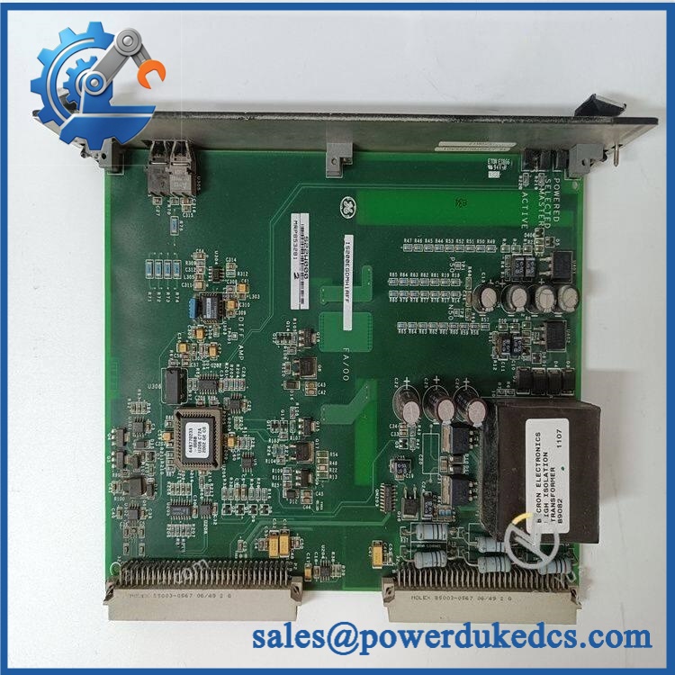
- GE IS200EGPAG1ABC
Module 4: Compatibility & Replacement Matrix
| Approval Item | Engineering Assessment |
|---|---|
| Replacement Classification | Drop-in Replacement within the matching GE EX2100 / IS200EGPA application, subject to hardware revision and cabinet configuration verification |
| Software Compatibility | Generally hardware-oriented; no routine firmware flash is identified for the EGPA board. Confirm the installed control-system revision and application documentation before commissioning |
| Hardware Modification | Not normally required when replacing the correct IS200EGPAG1A hardware form in the existing PCM |
| Estimated Swap Time | 2–6 hours for qualified maintenance personnel, excluding lockout/tagout, troubleshooting, and functional commissioning |
| Estimated Engineering Cost | 300–1,500 typical planning allowance for verification, installation support, and commissioning documentation |
| Downtime Exposure | Minimized when a tested spare is staged before outage work |
The EGPA is located in the Power Conversion Cabinet, one unit per power conversion module. The board receives commands from ESEL and is powered through EPDM, so replacement should be validated against the complete PCM architecture rather than treated as an isolated PCB swap.
⚠️ Field Traps — Watch Out
- Hardware Revision Mismatch: Verify the complete board identification, including the G1A hardware form and full suffix IS200EGPAG1ABC. Do not approve a visually similar IS200EGPA variant without confirming the application.
- Bridge Feedback / Thermal Wiring: The EGPA interfaces with bridge thermal and conduction-related signals. The documented thermal switch thresholds are 170°F alarm and 190°F trip; incorrect wiring or an incompatible bridge interface can create immediate fault conditions.
Module 5: Quality Assurance & Testing SOP
Every supplied IS200EGPAG1ABC should pass a documented inspection sequence before shipment:
- OEM anti-counterfeit visual inspection — verify GE markings, PCB identification, board revision, connectors, component condition, conformal coating, and manufacturing labels against known-good references.
- Part-number verification — record IS200EGPAG1ABC, hardware form, visible revision markings, and serial/traceability information.
- Connector and PCB inspection — check pins, edge connectors, terminal interfaces, solder joints, contamination, corrosion, and signs of prior overheating.
- Power integrity check — inspect the 125 VDC input path and onboard power-conversion circuitry for shorts, abnormal resistance, or physical damage before energized testing.
- Power-on self-test (POST) — energize the board in the appropriate EX2100 test setup and check ERR/RUN and status LED behavior against the applicable test procedure.
- Gate-drive functional testing — verify command reception and six-channel SCR firing-pulse behavior under controlled test conditions.
- I/O load testing — exercise applicable bridge feedback, thermal, airflow, and conduction-feedback interfaces; confirm expected response without nuisance alarms.
- Thermal protection verification — validate the alarm/trip sensing chain associated with the documented temperature-switch thresholds.
- Extended energized test — monitor operating behavior under load for abnormal temperature rise, intermittent faults, unstable outputs, or communication/interface anomalies.
- Final QC release — attach the test record, photograph the identification label, apply QC status, package in ESD protection, and retain traceability documentation.
The published technical references identify the EGPA as an gate-pulse board controlling six SCRs and interfacing with bridge monitoring functions, making functional testing more important than a cosmetic inspection alone.
Module 6: Procurement & Lifecycle FAQ
Q1. Is genuinely in stock, and what is the cutoff for emergency shipping?
Stock should be confirmed against the exact suffix before the PO is released. For emergency requirements, provide the quantity and destination before the daily dispatch cutoff so warehouse allocation and same-day carrier options can be checked. Do not treat a generic IS200EGPAG1A listing as confirmation of the ABC revision.
Q2. How do you verify the condition and authenticity of an obsolete or surplus ?
Each unit should receive part-number verification, OEM marking inspection, PCB and connector examination, electrical screening, energized functional testing where the test setup permits, and photographic traceability. The shipment package should include the applicable QC/test record rather than relying solely on a visual grading.
Q3. Are there firmware compatibility issues engineers should check before issuing the PO?
The primary concern is hardware and system configuration matching, not a routine EGPA firmware flash. Verify the exact EGPA hardware form, the installed ESEL/EPDM configuration, power-conversion-module arrangement, and bridge interface before approving the substitution.
Q4. What warranty and return terms should procurement require?
Require a written warranty covering the supplied board, with the warranty period stated on the quotation or order confirmation. For a failed-on-arrival claim, require serial/part-number traceability and a defined return authorization process. Warranty coverage should distinguish installation damage from an actual component failure.
Q5. Why purchase an spare instead of starting an modernization project?
When the existing excitation system remains serviceable, a verified replacement PCB can address a single-point failure without forcing the capital, engineering, testing, and outage scope of a complete control-system migration. The decision should be based on remaining installed-base support, critical-spares coverage, outage cost, and the expected service horizon of the generator.











 Start Chat


