

Description
- Brand: GE Industrial Systems
- Full Model Number: IS200EGPAG1BEC
- System/Series Family: EX2100 Excitation Control
- Core Function: Exciter gate pulse amplifier interfacing the EX2100 controller with the power bridge
- Top 3 Hardcore Specs: EGPA functional designation; gate firing for up to 6 SCRs; 125 VDC board input
- Functional Acronym: EGPA — Exciter Gate Pulse Amplifier
- Board Type: Bridge and protection board
- PCB Coating: Normal coating
- Revisions: Functional B / E; Artwork C
- Manual Reference: GEI-100461 / GEH-6632 series documentation
- Stock Status: New Surplus / Factory-Sealed or Fully Tested Refurbished subject to actual inventory condition
The IS200EGPAG1BEC is documented as a GE EX2100 Excitation Control Gate Pulse Amplifier. Its primary function is to interface the EX2100 control system with the power bridge and generate firing pulses for up to six SCRs.
Module 3: Technical Product Introduction
A gate-pulse failure in an excitation system can prevent the power bridge from correctly controlling field current, even when the upstream EX2100 controller remains operational. The GE IS200EGPAG1BEC is the EGPA Exciter Gate Pulse Amplifier used in the EX2100 excitation architecture. It receives gating commands from the associated control electronics and produces the firing-pulse interface for the bridge’s SCR devices. The board also participates in bridge monitoring functions, including temperature, airflow, and current-conduction feedback.
The complete suffix matters here. The IS200EGPAG1BEC is identified with functional revisions B and E and artwork revision C, while its board family is the normally coated G1 EGPA assembly. Documentation records also identify a 125 VDC input for the IS200EGPAG1B family and associate the board with manual GEI-100461. Do not substitute a generic EGPA board without checking the exact revision and bridge configuration.
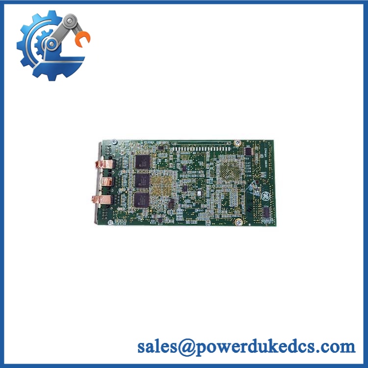
GE IS200EGPAG1BEC
Module 4: Application Scenarios & Field Realities
- At the excitation power bridge, the EGPA board provides the gate-firing interface for the SCR devices. If firing is lost on multiple bridge devices simultaneously, inspect the EGPA gating path and its upstream ESEL/control signals before replacing individual SCRs.
- When bridge temperature or airflow alarms appear, the EGPA circuit deserves inspection because the board interfaces with bridge monitoring functions. Thermal-switch arrangements can vary between installations—some systems use thermal switches while newer configurations may use RTDs.
- During generator excitation troubleshooting, compare the actual gate-pulse behavior with the controller’s command signals. A missing pulse can originate upstream, so a board replacement should follow confirmation of the control signal, board supply, and bridge-side conditions.
- For critical excitation-system spare inventory, preserve the complete IS200EGPAG1BEC identifier. GE’s family contains several visually similar boards, including other pulse-amplifier assemblies with different functions. The exact board reference and revision should remain on the purchase record.
Module 5: Migration, Compatibility & Installation Traps
Replacement Matrix
| Replacement Case | Classification | Engineering Requirement |
|---|---|---|
| IS200EGPAG1BEC → identical | Drop-in Replacement | Verify complete part number, revision, bridge configuration, and connector wiring |
| IS200EGPAG1B with documented compatible revision | Software Compatible | Confirm GE documentation and hardware configuration |
| Different EGPA revision or assembly configuration | Software/Configuration Verification | Compare revision, bridge interface, monitoring circuits, and application |
| Different pulse-amplifier family | Hardware Modification Required | Validate gate-drive, feedback, power, and connector interfaces |
Field Traps — Watch Out
1. Six SCR channels do not mean six independent excitation systems.
The EGPA board provides the gate-pulse interface for the SCR bridge. One source identifies the IS200EGPAG1B as controlling gate firing for up to six SCRs and notes that one EGPA board is required for each PCM in the applicable system architecture.
2. Check the bridge temperature-monitoring arrangement.
The configuration may use thermal switches or, in newer installations, an RTD arrangement. The EGPA interface therefore has to be matched to the actual bridge-monitoring architecture rather than assumed from the base board number alone.
Installation note: The excitation cabinet contains hazardous electrical energy. Follow the site’s electrical isolation and discharge procedure before removing the EGPA board. Preserve connector positions and record the original board revision before installation.

GE IS200EGPAG1BEC
Module 6: Quality Assurance SOP
For , QA should focus on exact revision identification, gate-pulse functionality, and bridge-monitoring interfaces.
- Part-number verification: Confirm on the physical PCB and purchasing record.
- OEM anti-counterfeit visual inspection: Examine GE markings, board number, serial/manufacturing information, PCB construction, connectors, component layout, and revision markings.
- Revision verification: Confirm Functional Revision B / E and Artwork Revision C where marked.
- Mechanical inspection: Check PCB edges, connectors, mounting points, terminal areas, jumpers, and board hardware.
- Component inspection: Look for overheated components, cracked semiconductor packages, corrosion, damaged connectors, loose hardware, or evidence of unauthorized repair.
- Power-on self-test (POST): Install the board in an approved test environment and verify startup behavior and applicable LED indications.
- Supply verification: Verify the applicable board supply against the approved GE documentation before energizing the test fixture.
- Gate-pulse verification: Apply controlled gating commands and confirm the expected output pulse behavior for the supported SCR channels.
- SCR interface verification: Test the gate-drive interface using an approved simulator or test fixture rather than an energized production bridge.
- Temperature monitoring verification: Simulate the applicable bridge temperature-monitoring inputs and verify alarm/trip response.
- Airflow monitoring verification: Exercise the applicable airflow-monitoring input and confirm the expected diagnostic response.
- Current-feedback verification: Verify the conduction-feedback path using a controlled test setup where applicable.
- Diagnostic verification: Check alarm and fault indications during normal and simulated fault conditions.
- Communication handshake verification: Verify the EGPA’s control-interface response to the associated control electronics.
- Final inspection: Recheck connectors, jumpers, labels, revision markings, PCB condition, and protective packaging.
- Traceability: Record the complete part number, functional/artwork revisions, serial information where available, test fixture, test results, inspection date, and condition classification.
Procurement note: The technically important identification is , not simply “GE EGPA.” The board belongs to the Excitation Control system and has a specific revision history. For a production excitation-system replacement, match the complete catalog number and verify the associated bridge and monitoring configuration before installation.











 Start Chat


