

Description
- Brand: GE
- Full Model Number: IS200EPSMG1AED
- Lifecycle Status: Legacy / Obsolescence-risk
- Core Function: Electrically isolated Exciter Power Supply Module for GE EX2100 excitation control
- Top 3 Technical Specs: 125 VDC input | +5 VDC, ±15 VDC, +24 VDC outputs | M1/M2/C controller power supply
- Stock & Condition: Physical stock confirmation required | New Surplus / Tested Refurbished by lot | Emergency dispatch subject to inventory and carrier cutoff
Module 3: Obsolescence & Supply Chain Deep Dive
A failed EPSM can remove control power from an EX2100 excitation channel, potentially taking one controller section out of service and extending generator-maintenance time. GE IS200EPSMG1AED is identified as an EX2100 Exciter Power Supply Module. Published technical records describe the IS200EPSMG1A family as converting 125 VDC from the EPDM into the DC voltages required by the control system, including +5 VDC, ±15 VDC, and +24 VDC. Three independent EPSM supplies are used to power the M1, M2, and C controller sections in the EX2100 architecture.
For an existing EX2100 installation, replacing the failed EPSM can preserve the established controller architecture and avoid a wider excitation-system modification. The board is electrically isolated and works with the EPBP power-backplane arrangement, so an exact replacement can reduce rewiring, cabinet changes, control-system revalidation, and generator commissioning work. (For legacy excitation equipment, verified physical inventory can be critical when the generator outage window is fixed.) The TCO calculation should include lost generation, electrical engineering, field labor, voltage verification, controller restart, and excitation functional testing rather than the spare-board price alone.
Module 4: Compatibility & Replacement Matrix
| Purchase Review Item | Engineering Guidance |
|---|---|
| Replacement Classification | Drop-in Replacement — conditional |
| Hardware Modification | None expected for an exact IS200EPSMG1AED configuration |
| Primary System | GE EX2100 Excitation Control System |
| Module Type | Electrically Isolated Exciter Power Supply Module |
| Input Voltage | 125 VDC |
| DC Outputs | +5 VDC, ±15 VDC, +24 VDC |
| Controller Allocation | M1, M2, or C controller power section |
| Backplane | EPBP |
| Typical Switch Time | ~2–6 labor hours including voltage and controller checks |
| Typical Engineering Cost | Approximately 400–1,200 excluding generator outage and site travel |
| Recommended Migration Path | Record EPSM position → verify input/output requirements → document wiring → isolate DC → replace → verify output rails → validate controller operation |
The available technical records identify the IS200EPSMG1A family as an electrically isolated power-supply module. The EPBP backplane provides dedicated EPSM connection points, and the architecture uses independent power supplies for the M1, M2, and C controllers.
Field Traps — Watch Out
- Controller-position mismatch: Verify whether the failed EPSM serves M1, M2, or C. The architecture uses separate supplies for these controller sections, so position and associated wiring must be documented before removal.
- Input/output verification: Confirm the existing DC input and all required output rails before installation. Do not approve a replacement based only on the IS200EPSMG1A family name; verify the complete IS200EPSMG1AED marking and board revision.
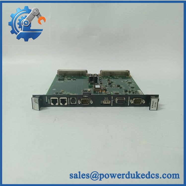
GE IS200EPSMG1AED
Module 5: Quality Assurance & Testing SOP
A strict pre-shipment inspection for GE IS200EPSMG1AED should include:
- Identity verification: Confirm the complete IS200EPSMG1AED part number, designation, board revision, serial information, connectors, and PCB markings.
- OEM anti-counterfeit visual inspection: Examine GE identification labels, PCB artwork, component placement, transformer and power circuitry, connectors, solder quality, and evidence of unauthorized repair.
- Mechanical inspection: Check the PCB, mounting points, edge connectors, terminal interfaces, and components for cracks, corrosion, contamination, overheating, or physical damage.
- Input-circuit inspection: Check the 125 VDC input path, terminals, protective components, and fuse-related circuitry before energization.
- Power-on self-test (POST): Install the EPSM in an approved test arrangement and verify normal startup and diagnostic behavior.
- Input-voltage test: Apply a controlled 125 VDC input and monitor current draw for abnormal behavior.
- Output-rail test: Verify +5 VDC, +15 VDC, -15 VDC, and +24 VDC outputs under no-load and representative-load conditions.
- Regulation test: Confirm output-voltage stability while applying representative controller loads.
- Isolation test: Verify the documented electrical isolation characteristics using an approved laboratory procedure.
- Load testing: Exercise each applicable DC output under controlled load while monitoring voltage, current, temperature, and ripple.
- Protection test: Verify appropriate response of the power circuitry to controlled abnormal test conditions without bypassing protective components.
- Controller simulation: Where the test fixture permits, connect representative M1/M2/C controller loads and confirm stable power delivery.
- Thermal run test: Operate the EPSM at representative load while monitoring component temperature, output drift, and abnormal heating.
- Extended run test: Monitor all output rails for intermittent dropout, resets, excessive ripple, or voltage instability.
- Final QC: Record serial number, revision, input voltage, measured output rails, load-test results, isolation-test results, condition grade, photographs, and packaging approval.
The EPSM is a power-conversion stage rather than a simple distribution board. A credible acceptance procedure therefore needs measured output-rail and load results, not merely a successful power-up.
Module 6: Procurement & Lifecycle FAQ
Is GE genuinely in stock, and what is the cutoff for emergency shipping?
Physical inventory should be confirmed against the exact marking before PO release. Current supplier records show this part listed as available, with one listing stating in-stock status, but emergency dispatch should be based on physically verified inventory, payment clearance, export documentation, and the carrier’s daily pickup cutoff.
How do you verify the condition and authenticity of this legacy power supply?
Require complete part-number and serial verification, OEM marking inspection, PCB examination, 125 VDC input testing, output-rail measurement, load testing, isolation verification, thermal testing, and documented final QC. New Surplus and Tested Refurbished units should be separately identified.
Can I replace with another EPSM variant?
Not automatically. The replacement must match the installed architecture, controller position, input arrangement, output-rail requirements, connectors, and board revision. Verify the complete board number before approving substitution.
Are there firmware compatibility issues I should warn my engineers about before issuing the PO?
Firmware is not normally the primary compatibility issue for an EPSM. The critical checks are 125 VDC input, required DC output rails, controller allocation, EPBP connection, polarity, wiring, and the exact board revision. Controller functionality should be verified after the power supply has been replaced.
What warranty and return terms should procurement require?
The quotation should specify the exact part number, revision, condition grade, serial traceability, electrical test scope, warranty period, DOA coverage, and return authorization procedure. For an excitation power module, the acceptance record should include measured input and output values under documented test loads.











 Start Chat


