

Description
- Brand: GE General Electric
- Full Model Number: IS200SDIIH1ADB MRP683026
- Lifecycle Status: Legacy / Obsolete Support
- Core Function: Mark VI Contact Input Isolation Terminal Board
- Top 3 Technical Specs: 72 screw terminals; dual-sided terminal layout; relay-based field interface with LED status indication
- Stock & Condition: New Surplus / Tested Refurbished; Physical stock confirmation required; Emergency dispatch subject to order cutoff
The IS200SDIIH1ADB MRP683026 is identified in current industrial references as a GE Contact Input Isolation Terminal Board associated with the Mark VI platform. Available board descriptions report terminal connections along both long edges, relay circuitry near the board center, and individual LEDs associated with relay-coil voltage. The part should be distinguished from similarly named Mark VI electronic I/O modules because it functions primarily as a field termination and isolation interface.
Module 3: Obsolescence & Supply Chain Deep Dive
A failed IS200SDIIH1ADB can interrupt multiple discrete field-input circuits while the main Mark VI controller remains operational. The board provides the physical termination and isolation interface between field devices and the Mark VI control system, making it important for applications involving contact status, interlocks, switches, and other discrete signals. Its large terminal count also means that replacing it incorrectly can introduce wiring errors across many points at once.
The TCO case favors a verified like-for-like replacement when the existing Mark VI cabinet, field wiring, and associated terminal arrangement remain serviceable. Keeping the original interface avoids extensive rewiring, panel modification, point-by-point engineering changes, and a prolonged commissioning cycle. This is especially valuable for legacy turbine-control cabinets where the documentation, field wiring, and installed hardware were designed around a specific board arrangement. A surplus replacement can shorten the recovery path considerably — although every terminal position should be checked against the existing wiring drawing before energization.
Module 4: Compatibility & Replacement Matrix
| Purchase Approval Item | Assessment |
|---|---|
| Replacement Classification | Conditional Drop-in Replacement |
| System Family | GE Mark VI |
| Module Type | Contact Input Isolation Terminal Board |
| Terminal Capacity | 72 screw terminals reported |
| Interface Type | Discrete contact-input field interface |
| Relay / LED Features | Relay circuitry with LED coil-voltage indication |
| Software Compatibility | Not normally applicable at terminal-board level |
| Hardware Modification | Normally not required for an exact replacement |
| Estimated Physical Changeover | 1–3 hours |
| Commissioning / Validation | Required for every transferred field circuit |
| Engineering Risk | High if terminal mapping is not preserved exactly |
Field Traps — Watch Out
- Terminal mapping error: With a high terminal count, a single shifted wire can create multiple false contact states or interlock faults. Photograph the original board, record every terminal designation, and verify the wiring point-by-point before removal.
- Variant confusion: Do not treat every IS200SDI family board as interchangeable. The MRP683026 identification should be matched in full, including suffix H1ADB, because similar Mark VI boards can serve different signal-interface functions.
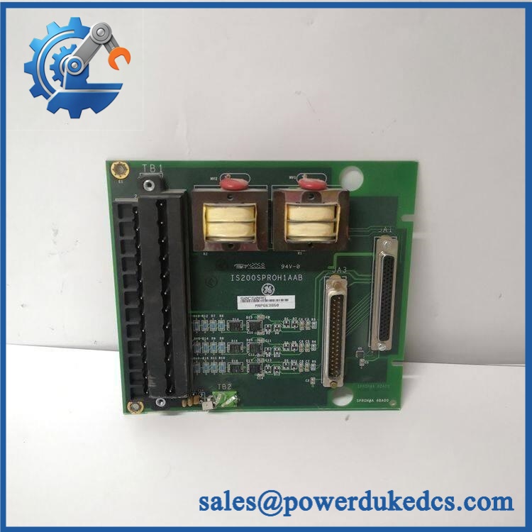
GE IS200SDIIH1ADB MRP683026
Module 5: Quality Assurance & Testing SOP
The board should be tested as a field-interface assembly rather than judged solely by PCB appearance.
- Incoming traceability: Record GE markings, complete IS200SDIIH1ADB MRP683026 identification, revision information, serial/lot data, and visible board codes.
- OEM anti-counterfeit visual inspection: Inspect PCB markings, labels, terminal construction, relay components, LEDs, connectors, solder quality, and evidence of prior repair.
- Mechanical inspection: Check mounting holes, terminal blocks, connectors, relay mounting, PCB edges, and board flatness.
- Power-on self-test (POST): Apply the approved control voltage in a controlled test setup and verify expected startup behavior.
- Supply verification: Measure applicable supply points and check abnormal current draw or localized heating.
- Terminal continuity test: Verify every applicable terminal path against the approved wiring map.
- Contact-input simulation: Apply controlled open/closed contact states across representative channels and verify correct state transmission.
- Full-channel testing: Where the test fixture permits, exercise the complete available terminal population rather than sampling only a few points.
- Relay verification: Confirm relay operation and expected coil-voltage LED indication.
- Isolation testing: Verify the intended separation between field circuits and the associated Mark VI interface using an approved laboratory procedure.
- I/O load testing: Apply representative field-side loads and monitor terminal stability, relay behavior, and temperature rise.
- Fault simulation: Introduce controlled open-circuit and short-circuit conditions on test channels and verify the expected diagnostic response.
- Extended operation: Run repeated input transitions while monitoring intermittent contacts, relay chatter, LED behavior, and thermal stability.
- Final QC release: Record terminal-map verification, channel results, relay results, inspection date, photographs, and technician approval.
Module 6: Procurement & Lifecycle FAQ
1. Is the GE IS200SDIIH1ADB MRP683026 genuinely in stock, and what is the cutoff for emergency shipping?
Current supplier listings show the exact part number as commercially available, but actual warehouse quantities vary. For an emergency requirement, confirm the physical unit, complete IS200SDIIH1ADB MRP683026 marking, condition, revision, and same-day dispatch cutoff before releasing the PO.
2. How do you verify the condition and authenticity of this surplus GE terminal board?
Verification should begin with the complete GE identification and physical inspection of the PCB, terminal blocks, relays, LEDs, connectors, and mounting features. Functional testing should then cover terminal continuity, simulated contact inputs, relay behavior, isolation checks, and representative load conditions. Photographs and measured results should be retained with the MRO record.
3. Are there any firmware compatibility issues I should warn my engineers about before issuing the PO?
No conventional firmware requirement normally applies to this type of terminal board. The key concern is hardware and wiring compatibility. Engineering should verify the exact board suffix, terminal numbering, associated Mark VI interface, field-voltage arrangement, and wiring documentation before installation.
4. Can the MRP683026 replace the existing board without hardware modification?
For an exact same-part replacement in the corresponding Mark VI cabinet arrangement, hardware modification is normally not required. The critical work is preserving the original terminal mapping and verifying every transferred field circuit before the system is returned to service.
5. What warranty and return terms should procurement require?
The PO should specify , exact revision, condition, test status, terminal configuration, warranty period, and return procedure. Warranty coverage should address DOA, terminal defects, and verified functional failure while excluding damage caused by incorrect field wiring, improper voltage, short circuits, ESD, installation errors, or unauthorized modification.











 Start Chat


