

Description
- Brand: GE / GE Energy
- Full Model Number: IS200STCIH6AED
- Lifecycle Status: Legacy / Obsolete
- Core Function: Simplex contact input terminal board
- Top 3 Technical Specs: 24 contact inputs; nominal 125 VDC excitation; DIN-rail or flat mounting
- Input Voltage: 125 VDC nominal
- Input Range: 100–145 VDC
- System Family: GE Mark VIe / Mark VIeS
- I/O Pack: One YDIA/PDIA-family discrete input pack
- Signal Type: Dry contact inputs
- Terminal Style: Pluggable terminal arrangement
- Input Architecture: Simplex
- PCB Function: Contact-input termination and signal conditioning
- Stock & Condition: New Surplus / Tested Surplus / Tested Refurbished subject to physical-unit confirmation
- Shipping: Emergency dispatch subject to confirmed stock and carrier cutoff
The GE IS200STCIH6AED is a simplex contact input terminal board used in the GE Mark VIe control architecture. The STCI family accepts 24 contact inputs, while the H6 configuration is associated with nominal 125 VDC excitation, with the documented operating range extending from approximately 100 to 145 VDC. The board is designed for DIN-rail or flat mounting and interfaces with a single discrete-input I/O pack.
The H6 configuration is particularly important for procurement because STCI boards are available in different voltage variants. A 24 VDC, 48 VDC, and 125 VDC STCI board may share a similar mechanical concept while serving different excitation-voltage requirements. The GE functional-safety documentation identifies the 125 VDC STCI version as the STCIS6A configuration, with 24 contact inputs and pluggable termination.
Obsolescence & Supply Chain Deep Dive
A failed IS200STCIH6AED can interrupt the acquisition of turbine auxiliary contacts, permissives, status signals, or other discrete field indications while the rest of the Mark VIe control system remains operational. Because the STCI family contains different voltage variants, simply sourcing another “STCI” board is not sufficient. The H6 version is associated with 125 VDC excitation, and replacing it with a lower-voltage STCI variant can produce incorrect threshold behavior or prevent the field contacts from being recognized correctly. For maintenance teams supporting an aging Mark VIe installation, the procurement target should therefore be the complete IS200STCIH6AED identification, not merely the STCI family name.
The TCO advantage comes from replacing the affected terminal board while retaining the existing I/O architecture, field wiring, cabinet arrangement, and control application. A targeted board replacement can avoid the engineering and outage cost of a broader control-system migration when the installed system remains serviceable. The board itself does not require conventional firmware loading; however, the I/O pack, terminal-board identity, excitation voltage, and simplex architecture must be verified before commissioning. The terminal board also contains an identification device used by the I/O processor, so incorrect hardware identification can result in a compatibility fault.
Compatibility & Replacement Matrix
| Buyer Review Item | IS200STCIH6AED Assessment |
|---|---|
| Exact-Part Replacement | Drop-in Replacement for an existing IS200STCIH6AED installation, subject to system verification |
| System Family | GE Mark VIe / Mark VIeS |
| Board Type | Simplex Contact Input Terminal Board |
| Contact Inputs | 24 |
| Excitation Voltage | 125 VDC nominal |
| Excitation Range | 100–145 VDC |
| Input Type | Dry contact / discrete input |
| I/O Architecture | Simplex |
| I/O Pack | One compatible discrete-input pack |
| Mounting | DIN rail or flat-panel mounting |
| Terminal Type | Pluggable |
| Firmware Flash | No routine terminal-board firmware flash requirement identified |
| Hardware Modification | Normally not required for an exact same-part replacement |
| Configuration Work | Required verification of voltage, wiring, I/O pack identity, and application mapping |
| Installation Labor | Approximately 1–3 hours as a planning allowance |
| Functional Verification | Approximately 2–4 hours depending on field access |
| Cross-Variant Replacement | Engineering verification required before using another STCI voltage variant |
The most important compatibility point is the excitation voltage. GE documentation distinguishes the STCI variants by voltage class, including 24 VDC, 48 VDC, and 125 VDC versions. The H6 configuration corresponds to the 125 VDC class.
Field Traps to Watch Out For
Excitation-voltage mismatch: Do not substitute a 24 VDC or 48 VDC STCI variant for the H6 125 VDC configuration without engineering approval. The contact-input threshold is tied to the applied excitation voltage, so using the wrong board variant can cause false OFF/ON interpretation.
I/O pack identification mismatch: The terminal board interfaces with a discrete-input I/O pack, and the terminal-board identification device stores information such as board type, serial number, and revision. A mismatch can trigger a hardware incompatibility fault. Verify the board and I/O pack combination before startup.
Simplex architecture limitation: STCI is intended for simplex applications. Do not substitute it into a redundant or safety architecture simply because the terminal connections appear similar. GE documentation distinguishes STCI from group-isolated TBCI architectures.
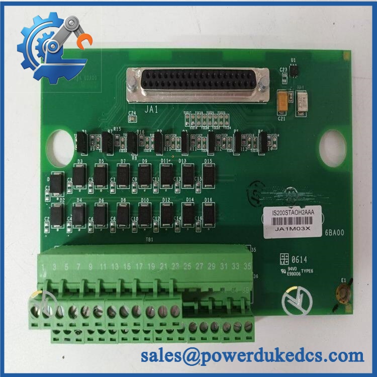
GE IS200STCIH6AED
Quality Assurance & Testing SOP
Part-number verification: Confirm the physical board marking as . Record the manufacturer, hardware revision, serial number, and all visible identification markings before testing.
OEM anti-counterfeit visual inspection: Inspect PCB layout, component population, board markings, labels, connector arrangement, terminal construction, mounting holes, and visible manufacturing characteristics against the approved GE reference. Any unexplained relabeling or PCB rework requires manual review.
Mechanical inspection: Examine the board and mounting assembly for cracks, deformation, corrosion, contamination, damaged mounting hardware, loose terminals, and evidence of excessive heat.
Terminal inspection: Inspect the full pluggable terminal assembly for bent contacts, oxidation, damaged clamps, loose hardware, and evidence of arcing. Preserve the original terminal position map before removing the installed board.
Configuration capture: Photograph every field connection and identify the excitation-voltage source before removal. Confirm that the installed system is actually using the 125 VDC H6 configuration.
Power-on self-test (POST): Install the board with the appropriate discrete-input I/O pack in an approved Mark VIe test environment. Apply controlled power and verify board recognition, initialization, status indication, and diagnostic behavior.
Contact-input simulation: Use a controlled switching fixture to exercise all 24 contact-input channels. Verify that each channel changes state correctly when the approved excitation circuit is opened and closed. Record each channel individually.
Voltage-threshold verification: Apply the appropriate 125 VDC nominal excitation source within the documented 100–145 VDC range and verify contact-state recognition at each tested channel. Do not exceed the approved test voltage.
Noise and transient testing: Where the laboratory fixture supports it, apply representative switching transients within the approved test procedure and verify that the input channels do not generate unexpected state transitions. The STCI architecture incorporates contact-input signal conditioning intended for this type of field environment.
I/O load testing: Operate representative contact circuits simultaneously and monitor the input pack for missed transitions, unstable states, communication faults, or unexpected diagnostics.
I/O pack identification check: Confirm that the I/O processor correctly recognizes the terminal board identification data. Any hardware incompatibility indication places the unit on hold for engineering review.
Grounding verification: Check the board mounting and grounding arrangement according to the approved cabinet design. Verify that shield and grounding conductors are routed correctly and are not inadvertently bonded to signal terminals.
Final QA release: Record exact model, revision, serial number where available, terminal configuration, excitation voltage, 24-channel test results, I/O pack recognition status, POST result, technician, and test date. Approved units are packaged using ESD protection and suitable mechanical cushioning.
Procurement & Lifecycle FAQ
Is the genuinely in stock and what is the cutoff for emergency shipping?
The model is still offered by secondary industrial inventory suppliers, but real-time physical stock should be confirmed against the actual unit before an emergency PO is released. Confirm quantity, exact suffix, condition, revision, warehouse location, destination, and carrier cutoff before payment.
How do you verify the condition and authenticity of an obsolete ?
The acceptance process should include exact model and revision verification, PCB and terminal inspection, physical nameplate review, I/O pack identification verification, controlled power-up, and a complete 24-channel contact-input test. Commercial condition should be stated clearly as New Surplus, Tested Surplus, or Tested Refurbished.
Are there any firmware compatibility issues I should warn my engineers about before issuing the PO?
No routine terminal-board firmware-flash requirement has been identified. The principal compatibility checks are the 125 VDC excitation class, simplex architecture, correct discrete-input I/O pack, and terminal-board identification data. The board’s identification information is read by the I/O processor, making exact hardware verification important.
Is the a direct replacement for an installed unit?
An exact replacement can generally be treated as a drop-in replacement at the terminal-board level when the existing system uses the same H6 configuration. Engineers should verify excitation voltage, terminal wiring, I/O pack type, board identification, and simplex architecture before returning the system to operation.
What warranty and return terms should procurement require?
The PO should specify the exact part number, revision, physical condition, inspection status, warranty period, DOA definition, return period, and return-freight responsibility. For legacy GE Mark VIe hardware, retain actual-unit photographs and the complete pre-shipment test record with the procurement documentation.











 Start Chat


