

Description
- Model & Brand: IS200TREGH1BEC | GE
- Series: Mark VI Speedtronic
- Part Type: Turbine Emergency Trip Terminal Board
- Functional Acronym: TREG
- Primary Application: GE turbine emergency-trip and protection system
- Application Voltage: 125 VDC trip circuit
- Relay Count: 12 total relays
- Trip Solenoid Capacity: 3 emergency trip solenoids per TREG board
- Physical Dimensions: Approx. 178 × 330 mm board envelope; depth depends on terminal hardware and installed connectors.
- Estimated Net Weight: Approx. 0.5–0.8 kg
- Estimated Shipping Weight: Approx. 1.0–1.5 kg with ESD packaging and rigid carton
- What’s in the Box: TREG board; ESD shielding bag; protective packaging; terminal hardware and mating cables only when specifically included
- Main Connectors: 3 × 37-pin D-shell connectors
- Field Interface: 2 barrier-type terminal blocks
- Protection Components: 12 MOVs
- Installation: Internal Mark VI turbine-protection cabinet
Product Introduction
Emergency-trip hardware must remain electrically predictable under fault conditions. GE IS200TREGH1BEC is the Turbine Emergency Trip Terminal Board used in the Mark VI turbine-protection architecture. It interfaces between the VPRO protection electronics and the field emergency-trip circuitry, supporting up to three trip solenoids. The board provides the positive side of the 125 VDC trip circuit, while the associated TRPG arrangement provides the complementary side. ([GE Mark VI technical documentation])
The board contains 12 relays, with nine arranged as three groups of three for voted trip control, plus three economizer relays. ([GE Mark VI technical documentation]) The H1B configuration is associated with the 125 VDC application, while the BEC suffix identifies a specific hardware revision/configuration. This is a protection-path component, not a standard process-I/O terminal board (exact wiring and revision matching should therefore be treated as mandatory).
Core Technical Specifications
| Parameter | Value |
|---|---|
| Manufacturer | GE |
| Part Number | IS200TREGH1BEC |
| Series | Mark VI Speedtronic |
| Functional Acronym | TREG |
| Product Type | Turbine Emergency Trip Terminal Board |
| Primary Function | Emergency trip solenoid interface and power distribution |
| Trip Circuit Voltage | 125 VDC |
| Trip Solenoids Supported | 3 |
| Total Relays | 12 |
| Voting Relays | 9, arranged in 3 groups of 3 |
| Economizer Relays | 3 |
| Relay Coil Supply | 28 VDC from associated VPRO protection electronics |
| Solenoid Current | Approximately 1 A nominal energizing current |
| Solenoid Operating Range | Approximately 70–145 VDC |
| Economizer Resistor | 10 Ω, 70 W |
| Solenoid L/R Time Constant | Maximum approximately 0.1 s |
| Suppression | MOV suppression across solenoid circuits |
| Main Connectors | 3 × 37-pin D-shell |
| Field Terminal Blocks | 2 barrier-type terminal blocks |
| MOV Count | 12 |
| Board Dimensions | Approx. 178 × 330 mm |
| Processor | None |
| Standalone Firmware | None |
| Protection Architecture | Independent emergency turbine protection |
| Associated Hardware | VPRO / TRPG / applicable termination assemblies |
| Lifecycle | Legacy / obsolete Mark VI spare |
The Mark VI documentation identifies TREG as the Turbine Emergency Trip Terminal Board and shows its connections to VPRO, TRPG, and emergency-trip field circuitry. ([GE Mark VI technical documentation])
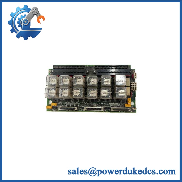
GE IS200TREGH1BEC
🚨 Global Compliance & Industry Certifications
The IS200TREGH1BEC is part of a turbine protection installation, so compliance has to be documented against the complete Mark VI system and actual hardware configuration.
- CE Mark: No standalone CE declaration specific to IS200TREGH1BEC was established from the records reviewed.
- UL/cUL: No independent UL/cUL listing specific to this exact DS200/IS200 board was established.
- ATEX/IECEx: No standalone ATEX or IECEx certificate for this exact TREG board was established.
- Marine Approvals: No board-specific DNV, ABS, or Lloyd’s Register approval was established.
- EMC: Final performance depends on the complete protection cabinet, grounding, shielding, field wiring, and installation arrangement.
- Safety Function: The board participates in the independent emergency-trip path; replacing it with an undocumented alternative can affect the validated turbine protection architecture.
The 125 VDC trip circuit is particularly important from a safety and audit standpoint. The board interfaces with high-energy trip circuits and must retain the approved insulation, wiring, relay, suppression, and terminal arrangement.
Verify specific lot certifications with OEM.
🚨 Long-Term Storage & Asset Preservation Guide
Keep the IS200TREGH1BEC sealed in an ESD shielding bag. The assembly includes relays, MOVs, capacitors, semiconductors, and multiple connector interfaces. Static exposure or contamination around the contacts can create failures that only appear after energization.
Control humidity below approximately 60% RH where practical. The terminal blocks and relay contacts are particularly sensitive to corrosion and contamination during extended storage. Avoid condensation during movement from cold warehouses into warm maintenance areas.
Protect the relay and connector hardware mechanically. Do not stack heavy boards on the barrier terminal blocks or D-shell connectors. Damage to one connector contact can compromise a protection channel without obvious PCB damage.
Record the exact board configuration. Photograph the nameplate, revision, terminal connections, connector positions, and any visible jumpers before shelving. This becomes valuable evidence when the spare is deployed years later.
Do not cycle the relays unnecessarily during storage. Relay exercise should be part of a controlled functional test, not an arbitrary warehouse-preservation routine.
Do not apply a generic capacitor-reforming schedule. No board-specific reforming interval was established in the reviewed documentation. Use controlled electrical testing before releasing a long-stored spare for turbine service.
Physical Installation Prerequisites
The is an internal Mark VI turbine-protection terminal board, not a DIN-rail assembly.
Before installation:
- Confirm the host system uses the appropriate GE Mark VI VPRO emergency-protection architecture.
- Verify the exact nameplate and hardware revision.
- Isolate the turbine and all associated electrical energy sources according to the approved LOTO procedure.
- Verify absence of 125 VDC trip-circuit energy before touching the field terminals.
- Label every field conductor before disconnecting the existing board.
- Photograph all three 37-pin D-shell connections.
- Inspect both barrier terminal blocks for loose hardware, damaged insulation, or corrosion.
- Confirm the three trip-solenoid circuits against the approved turbine wiring diagram.
- Verify the associated TRPG and VPRO arrangements before reconnection.
- Check relay and MOV components for heat damage or discoloration.
- Preserve the original grounding and shield arrangement.
- Use ESD controls throughout board handling.
- Maintain the original cable-routing paths to limit electrical noise and mechanical strain.
- Do not impose a generic 50 mm clearance around the PCB. Cabinet ventilation and service space should follow the actual Mark VI installation.
- Confirm the solenoid voltage and current requirements before energizing.
- Perform point-to-point wiring verification before restoring the emergency-trip circuit.
- Complete a controlled emergency-trip functional test after replacement.
The documented TREG architecture shows connections to VPRO, TRPG, TSVO, and an optional second TREG board, with the field interface implemented through barrier terminals. ([GE Mark VI technical documentation])
Buyer’s FAQ
Q1. What HS tariff code should be used for GE ?
A: A current industrial inventory record classifies this part under HS 85389091, but a supplier’s code should not be treated as universally binding. Because the item is a dedicated electrical protection/control component, classification under the appropriate national subdivision of HS heading 8538 may be considered. The importer or customs broker should confirm the final code for the destination country.
Q2. Does Country of Origin equal the location where the board is currently stored?
A: No. COO concerns the applicable manufacturing-origin rules for the actual board, not the export warehouse. One current industrial record identifies United States origin for this part. For audit purposes, retain the actual board identification and supporting origin documentation with the commercial invoice and Certificate of Origin when required.
Q3. How should I pack and insure for international freight?
A: Use an ESD shielding bag, rigid protection around all three D-shell connectors and both terminal blocks, internal shock absorption, and moisture protection appropriate for the route. Published supplier records report roughly 0.8 kg for one packed unit, but the actual shipment should be weighed before booking. For a turbine protection spare, insurance should cover the full declared replacement value.
Q4. Does include the latest firmware pre-loaded?
A: No. The TREG is a terminal and relay interface board, not a standalone processor. It contains no conventional application firmware. The relevant software resides in the associated Mark VI protection/control hardware. The board’s critical configuration attributes are its hardware revision, wiring arrangement, relay architecture, and relationship to VPRO/TRPG equipment.
A: No. This board participates directly in a 125 VDC emergency-trip circuit and interfaces with turbine shutdown solenoids. Perform the replacement under a fully approved shutdown and isolation procedure, verify the trip circuit is de-energized, document all terminal and D-shell connections, then execute a controlled trip-path test before returning the turbine to service.











 Start Chat


