

Description
- Brand: GE
- Full Model Number: IS200TRLYH1BGF
- System/Series Family: GE Mark VI Turbine Control System
- One-Sentence Core Function: Relay termination board providing discrete relay-output interfacing between the Mark VI control system and field devices
- Top 3 Hardcore Specs: 12 relay-output circuits; 48 field terminals; H1B TRLY relay-board architecture with coil sensing
- Stock Status: New surplus / fully tested refurbished, subject to exact hardware revision
GE technical documentation identifies the TRLYH1B as a relay-output terminal board holding 12 plug-in magnetic relays. The board supports simplex and TMR Mark VI configurations through its associated control and I/O architecture.
Module 3: Commercial-Technical Deep Dive
A failed relay termination board can interrupt discrete control signals even when the Mark VI controller itself remains fully operational. The GE IS200TRLYH1BGF belongs to the Mark VI TRLY family and provides the field-side relay interface for turbine control outputs. The H1B configuration contains 12 relay-output circuits, with the board using plug-in magnetic relays and associated suppression and monitoring circuitry. GE documentation describes the TRLYH1B architecture as supporting relay-output applications where the control system commands external devices such as solenoids and other discrete loads.
For maintenance planning, the channel count is the important number: 12 relay outputs are available from one board, with 48 customer-facing terminals arranged across two terminal blocks. The board can use customer-supplied power or configured solenoid power arrangements depending on the installation, and the relay circuits include monitoring functions. That means a correct replacement can restore the existing field interface without rewriting the turbine application. Do not, however, substitute an H1B board for an H1D, H1E, or H1F variant merely because the connector pattern looks similar—those variants implement materially different output architectures.
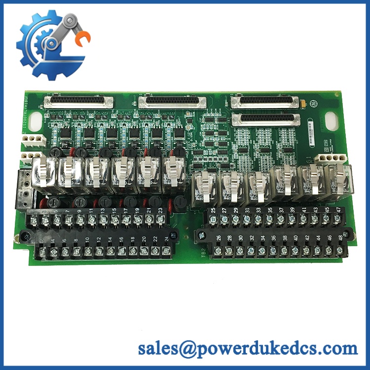
GE IS200TRLYH1BGF
Module 4: Compatibility & Installation Traps
Migration/Compatibility
- Replacement type: GE Mark VI termination relay board
- Model: IS200TRLYH1BGF
- Functional family: TRLYH1B
- Firmware flash: Not applicable to the passive relay termination board itself
- Logic rewrite: Not normally required for a same-board replacement
- Drop-in status: Generally suitable when replacing the identical TRLYH1B hardware revision in the same Mark VI configuration
- System architecture: Compatible with Mark VI output architectures controlled through the appropriate VCCC, VCRC, or related control hardware; the associated I/O configuration must be verified before replacement.
- I/O capacity: 12 relay outputs and 48 field terminals
⚠️ Field Traps (Watch Out)
1. Verify the exact TRLY variant before installation.
GE documentation distinguishes TRLYH1B from later variants such as TRLYH1D, TRLYH1E, and TRLYH1F. H1E, for example, uses solid-state relays, while H1F provides TMR contact voting. These are not generic drop-in equivalents.
2. Check relay-power configuration and jumpers.
The H1B board can use different power arrangements for relay outputs. GE documentation specifies jumper and fuse configurations for the relay circuits and identifies dedicated solenoid-power connections. Record the original jumper and fuse arrangement before removing the board.
3. Verify terminal labeling before reconnecting the field wiring.
The board uses two terminal blocks with 24 terminals each, giving 48 field terminals. Misplacing a single conductor can energize the wrong field device, so photograph and label every conductor before replacement.
4. Do not infer load ratings from the board family alone.
The actual permitted relay-contact voltage and current depend on the field circuit and relay configuration. Use the GE wiring documentation for the exact application rather than applying a generic relay rating to every channel.
Module 5: Quality Assurance SOP
Each GE IS200TRLYH1BGF unit should pass a documented pre-shipment inspection sequence:
- OEM anti-counterfeit visual inspection: Verify GE identification, IS200TRLYH1BGF marking, TRLYH1B designation, board revision, relay arrangement, connector layout, and PCB manufacturing markings.
- Part-number verification: Match the complete part number against the purchase order and installed Mark VI BOM where available.
- Revision inspection: Confirm the H1B functional revision and record all visible secondary codes before release.
- Mechanical inspection: Check both 24-terminal field blocks, relay sockets, connector bodies, mounting points, PCB surface, and board coating for damage, corrosion, contamination, or unauthorized repair.
- Relay inspection: Verify that all installed relay positions are populated correctly and inspect relay covers and sockets for physical damage.
- Power-path inspection: Check fuse positions, jumpers, terminals, suppression components, and accessible power traces for discoloration or thermal damage.
- Power-on self-test (POST): The TRLY board itself does not provide an independent CPU-style POST. When installed in an approved Mark VI test environment, verify the expected controller diagnostic state and relay-board identification.
- Relay functional test: Exercise each applicable relay channel individually and verify the expected contact transition using a controlled test fixture.
- Field-voltage verification: Where the test setup permits, verify relay-contact sensing and the configured supply arrangement without exceeding the specified circuit limits.
- Communication handshake verification: The passive TRLY board does not provide an independent network interface. Verify controller-to-I/O operation at the Mark VI system level and confirm that expected relay commands reach the board.
- Final QC: Photograph the nameplate, record relay-channel test results, document jumper/fuse configuration, protect the terminal blocks and connectors, and package the board in ESD-safe material.
Module 6: CRO-Driven Buyer FAQ
1. What is GE IS200TRLYH1BGF?
The is a GE Mark VI termination relay board belonging to the family. Its primary function is to interface discrete turbine-control outputs with field relay circuits. GE documentation identifies the H1B board as a 12-relay-output terminal board.
2. How many relay outputs does the provide?
The H1B configuration provides 12 relay outputs and uses 48 customer-facing terminals across two terminal blocks.
3. Can the be hot-swapped?
Do not assume hot-swap capability. The TRLY board interfaces directly with field relay and solenoid circuits, so replacement should follow the applicable GE Mark VI maintenance procedure, including isolation of the relevant field power and verification of de-energized circuits before disconnection.
4. Is interchangeable with TRLYH1E or TRLYH1F?
No. The architectures differ. GE documentation describes TRLYH1E as a solid-state relay board, while TRLYH1F provides TMR contact voting. These functions are materially different from the H1B mechanical-relay architecture.
5. What warranty and technical support are provided?
Warranty duration should be stated on the quotation for the exact inventory condition supplied. Technical support should cover part-number and revision verification, relay-channel testing, terminal/jumper configuration checks, inspection records, and replacement guidance within the documented Mark VI architecture. Field rewiring, turbine logic changes, and energized commissioning remain the responsibility of qualified site personnel.











 Start Chat


