

Description
- Brand: GE General Electric
- Full Model Number: IS200TRPGH1BDD / S1C5029
- System/Series Family: Mark VI Speedtronic Turbine Control
- One-Sentence Core Function: Primary trip terminal board used to interface turbine protection logic with trip solenoids and associated flame-detector circuits
- Top 3 Hardcore Specs: -125 VDC trip-solenoid feed; 3 trip-solenoid relay paths; TREG/TRPG turbine-protection architecture
- Stock Status: New Surplus / Fully Tested Refurbished — exact TRPG revision and field-interface configuration verified before shipment
Module 3: Commercial-Technical Deep Dive
A TRPG failure is not an ordinary I/O-card problem. This board sits directly in the turbine protection chain, where a fault can affect the path used to de-energize trip solenoids. The GE IS200TRPGH1BDD S1C5029 is a Primary Trip Terminal Board in the Mark VI Speedtronic turbine-control architecture. GE-oriented technical references identify the TRPG board as the interface for three main trip solenoids, with J1 receiving the 125 VDC trip-solenoid supply and J2 supplying the associated TREG board. In TMR applications, the main protection relays form a hardware two-out-of-three voting arrangement.
The important replacement specification is therefore the protection architecture, not a generic “power board” description. The H1BD/BDD assembly is a terminal-board configuration used with Mark VI turbine protection hardware, while the installed TREG/ TRPG arrangement, field wiring, relay paths, and turbine-specific flame-detector configuration determine actual behavior. Current references also identify MOV-based suppression around the trip-relay circuits. One technical listing describes three D-shell interfaces and two terminal strips for field connections, but these mechanical details should be verified against the actual board revision before being used for cabinet documentation.
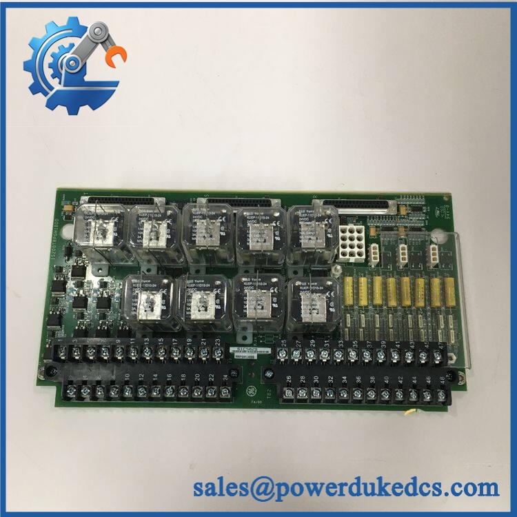
GE IS200TRPGH1BDD
Module 4: Compatibility & Installation Traps
Migration/Compatibility
- Replacement status: Configuration-specific Mark VI primary trip terminal board.
- Functional identity: TRPG = Primary Trip Terminal Board; it should not be classified as a standalone PLC power module.
- Trip architecture: Works with the TREG turbine-protection circuitry and the associated trip-solenoid wiring.
- Firmware requirement: No independent firmware update is normally associated with the passive/interface terminal board itself. The controlling Mark VI hardware and application configuration remain separate.
- Logic rewrite: Normally not required for a true like-for-like board replacement. Protection voting, trip logic, and associated I/O configuration must still be validated before returning the turbine to service.
- Revision control: Match IS200TRPGH1BDD exactly. Do not substitute another TRPG revision without checking the hardware drawing and installed cabling.
⚠️ Field Traps (Watch Out)
- 125 VDC trip circuit: The TRPG interfaces directly with turbine trip-solenoid circuitry. Verify the actual plant trip-voltage architecture before touching the board; do not infer safety from the low-voltage control electronics.
- TREG relationship: The TRPG and TREG boards form part of the turbine protection path. Incorrect replacement or cabling can prevent a legitimate trip command from reaching the intended solenoid path.
- TMR voting: In TMR systems, verify the complete two-out-of-three relay path after replacement. A healthy individual relay does not prove the overall protection vote is correct.
- Field wiring: Photograph the three trip-solenoid connections, flame-detector connections where fitted, and every cable position before removal. Connector labels alone are not sufficient when cabinet modifications exist.
- MOV suppression: Inspect the suppression components around the trip-relay circuits for cracking, discoloration, or previous overvoltage damage.
- ESD and LOTO: Use grounded ESD procedures for the PCB while applying the plant’s full turbine electrical-isolation and LOTO procedure for the energized trip circuitry.
Module 5: Quality Assurance SOP
Our pre-shipment inspection for a GE IS200TRPGH1BDD S1C5029 concentrates on identity, relay paths, terminal integrity, and protection-circuit condition:
- OEM anti-counterfeit visual inspection — verify GE identification, full IS200TRPGH1BDD marking, S1C5029 identification, PCB artwork, revision markings, terminal strips, connectors, and manufacturing labels.
- Part-number capture — photograph front/rear labels and every secondary identification marking before testing.
- Revision verification — confirm the BDD revision against the customer’s removed board and applicable Mark VI hardware documentation.
- PCB condition inspection — inspect solder joints, terminal blocks, relay packages, MOV suppression components, connectors, contamination, corrosion, and thermal discoloration.
- Trip-circuit inspection — verify the integrity of the three trip-solenoid relay paths and associated connector/terminal hardware.
- Power-on self-test (POST) — where a compatible Mark VI test environment is available, apply the documented auxiliary conditions and monitor board status, abnormal current draw, and diagnostic behavior.
- Relay continuity test — verify the specified normally open/normally closed contact transitions under controlled, de-energized test conditions.
- Trip-path simulation — simulate representative protection commands and confirm correct relay-path response without connecting the test fixture to live turbine trip solenoids.
- TREG interface verification — where the test environment supports it, verify the TRPG-to-TREG interface and expected status feedback.
- Flame-detector path check — where fitted, verify the relevant connector and signal paths against the customer’s actual cabinet configuration.
- MOV inspection — inspect and electrically screen the available suppression components for obvious short/open conditions or physical deterioration.
- TMR verification — for TMR applications, verify each available trip path and confirm the intended voting architecture with the approved test procedure.
- Extended observation — monitor relay stability, terminal integrity, intermittent contacts, and abnormal heating during controlled testing.
- Configuration record — document part number, revision, serial identification, test fixture, relay results, and photographs.
- Final QC review — cross-check all recorded identifiers against the customer’s exact Mark VI spare requirement.
- ESD packaging — protect the PCB, terminals, and connectors against ESD, impact, dust, and moisture before shipment.
The manufacturer-family evidence establishes the key functional point: TRPG is the primary trip terminal board, with three main trip-solenoid paths and a defined relationship to TREG and the turbine protection logic.
Module 6: CRO-Driven Buyer FAQ
1. Is GE IS200TRPGH1BDD S1C5029 obsolete, and how do I verify authenticity?
The belongs to GE’s legacy Mark VI Speedtronic turbine-control platform. Verify the complete board number, BDD revision, S1C5029 marking, PCB layout, terminal arrangement, and connector population. A photograph of the customer’s installed TRPG board is the safest pre-order reference.
2. What does the TRPG board actually control?
TRPG is the Primary Trip Terminal Board. Its protection-side function includes the main trip-solenoid interface, with technical references describing three trip-solenoid circuits and the associated TREG interface. Flame-detector connections may also be present depending on the installed configuration.
3. Is the trip-solenoid circuit 125 VDC?
Technical references for the TRPG architecture identify 125 VDC at the J1 trip-solenoid supply connection. Treat this as a plant-level hazardous control circuit and verify the actual cabinet documentation before maintenance.
4. Can be hot-swapped?
Do not treat it as a hot-swappable I/O module. TRPG is part of the turbine protection chain and interfaces with trip-solenoid circuitry. Perform the approved turbine shutdown/isolation procedure, verify the applicable trip circuit is safe to work on, and follow the site’s LOTO and protection-system change-control requirements.
5. Is the board used in TMR Mark VI systems?
Yes. Technical documentation for the TRPG architecture describes support for both simplex and TMR arrangements, with TMR using a hardware two-out-of-three voting path for the main protection trip relays.
6. What warranty and technical support should I expect?
Warranty duration should be stated on the quotation for the exact physical board supplied. Technical support should cover part-number and revision matching, TRPG/TREG compatibility, terminal identification, relay testing, and documented pre-shipment inspection results. It should not substitute for turbine-protection engineering, trip-circuit validation, or final commissioning by qualified personnel.











 Start Chat


