

Description
- Model & Brand: IS200VCRCH1B / GE General Electric
- Series: Mark VI Speedtronic
- Part Type: VCRC Contact Input / Relay Output Board
- Core Function: Interfaces 48 discrete contact inputs and relay-output circuits with the Mark VI VME I/O rack
- Input Capacity: Up to 48 discrete contact inputs through two TBCI terminal boards
- Relay Capacity: Up to 24 relay outputs through two TRLY terminal boards
- VME Format: Single-slot VME board
- Front Connectors: J33 and J44 for TBCI contact-input connections
- Relay Interface: Relay outputs use J3/J4 connections on the VME rack
- Diagnostic LEDs: RUN, FAIL, STATUS
- Approx. Dimensions: Supplier records report approximately 11.0 × 7.5 in (279 × 190.5 mm); verify the installed hardware drawing before cabinet planning
- Estimated Shipping Weight: Approximately 1.0–1.4 kg packed, depending on ESD and connector protection
- What’s in the Box: board, ESD shielding, rigid cushioning, identification materials; cables and terminal boards only when specifically included
- Mounting: VME rack
- Storage: Dry, ESD-controlled environment with connector protection
The GE Mark VI system guide identifies the VCRC as a single-slot contact input/relay output board with the same functional role as the double-width VCCC, while current technical records identify as the VCRC board with J33/J44 front-panel connections.
Product Introduction
The VCRC is the compact Mark VI interface between field contact wiring, relay termination boards, and the VME I/O rack. receives contact inputs from the TBCI terminal boards through J33 and J44, while relay outputs from TRLY terminal boards reach the VME rack through the J3/J4 connections. GE documentation states that the VCRC performs the same basic function as VCCC without requiring the VCCC daughterboard, allowing the assembly to occupy only one VME slot.
For asset control, that physical distinction is important. VCRC saves rack space, but its relay-output cabling is routed through the front panel/VME-rack J3 and J4 connections, unlike an arrangement where VCCC provides a different cable-routing method. The board also contains active logic, FPGAs, RAM devices, power supplies, and diagnostic LEDs, so it should not be treated as a passive terminal adapter (especially when troubleshooting a simultaneous loss of several contact and relay channels).
Core Technical Specifications
| Parameter | Value |
|---|---|
| Manufacturer | General Electric |
| Part Number | |
| Series | Mark VI Speedtronic |
| Functional Acronym | VCRC |
| Product Type | Contact Input / Relay Output Board |
| VME Slots | 1 |
| Contact Inputs | Up to 48 discrete inputs |
| TBCI Connections | J33, J44 |
| Relay Outputs | Up to 24 through TRLY boards |
| Relay Connections | VME rack J3, J4 |
| Relay Board Association | TRLY |
| Contact Board Association | TBCI |
| Contact Input Supply | DC-wetted field contacts |
| SOE Capability | High-speed scanning for critical contact inputs |
| Diagnostic LEDs | RUN, FAIL, STATUS |
| Backplane Interfaces | VME |
| Logic Devices | FPGA, SRAM/RAM |
| Power Supplies | 2 onboard supply sections reported |
| PCB Technology | Conformal-coated variant reported for H1B |
| Hardware Form | B |
| Functional Revision | B |
| Artwork Revision | A |
| Group | H1 |
| Mounting | VME I/O rack |
| Firmware | VCRC system firmware/configuration dependent |
| Approx. Dimensions | Supplier-reported; verify against actual assembly |
| Heat Dissipation | Host VME rack and cabinet dependent |
GE’s system guide documents 24 contact inputs per TBCI board, two TBCI boards for 48 inputs, and relay outputs through two TRLY boards, while the VCRC itself occupies one VME slot. It also states that VCRC firmware, configuration, and specifications are the same as those of VCCC.
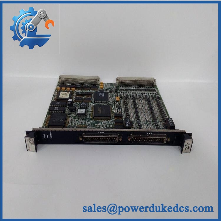
GE IS200VCRCH1B
🚨 Global Compliance & Industry Certifications
For this board, compliance should be controlled at the complete Mark VI cabinet/system level unless GE documentation explicitly assigns certification to the exact board revision.
- CE Mark: May apply to the complete Mark VI equipment. Do not claim independent CE conformity for without revision-specific GE documentation.
- UL/cUL: Do not claim independent UL/cUL listing for the bare board without applicable GE certification evidence.
- ATEX / IECEx: No independent ATEX or IECEx certification was established for this specific VCRC board from the reviewed records.
- Class I, Division 2 / Zone 2: Applicability depends on the complete Mark VI installation, enclosure, terminal boards, wiring, and approved system configuration.
- Marine Approvals: No DNV, ABS, or Lloyd’s Register approval was established for from the records reviewed.
- EMC: The VCRC contains active digital logic and interfaces with several field-wiring assemblies; EMC compliance should therefore be evaluated as part of the complete Mark VI cabinet.
Why this matters: TBCI inputs may monitor turbine permissives, trips, interlocks, and critical status contacts, while TRLY outputs can drive external relay circuits or solenoids. An undocumented revision can therefore create a maintenance and compliance problem even when the board powers up normally.
Verify specific lot certifications with OEM.
🚨 Long-Term Storage & Asset Preservation Guide
Keep the VCRC in an ESD shielding bag. The board contains FPGA/RAM devices, onboard power supplies, connectors, and exposed VME interfaces. Protect the edge contacts and front-panel connectors from impact during warehouse handling.
Keep relative humidity below 60% where practical. Avoid condensation and prolonged temperature cycling. Oxidation at VME contacts or front-panel connector pins can produce intermittent I/O failures that look like field wiring problems.
Preserve the VCRC-to-terminal-board mapping with the asset. Store the spare with documentation showing the associated TBCI and TRLY boards, plus photographs of J33/J44 and the relevant J3/J4 routing. The Mark VI architecture depends on those specific interconnections.
Before energized testing after years of storage, allow the sealed package to reach room temperature. Inspect the VME edge connector, J33/J44 connectors, diagnostic LEDs, board coating, solder joints, and onboard power-supply area.
Physical Installation Prerequisites
- Host System: Install only in the approved GE Mark VI VME I/O rack.
- Rack Space: VCRC uses one VME slot. Verify the exact rack position against the Mark VI cabinet drawing.
- Contact Inputs: Confirm the two TBCI boards and their J33/J44 cable mapping before removing the old board.
- Relay Outputs: Verify the TRLY boards and the corresponding J3/J4 VME-rack connections.
- Cable Routing: Ensure front-panel relay cables have adequate bend radius and do not interfere with adjacent VME cards.
- Power Isolation: GE documentation specifies powering down the processor rack before board installation.
- Grounding: Preserve the Mark VI cabinet protective-earth and signal-reference arrangement.
- Clearance: Leave enough front access for J33/J44 cable removal and secure seating of the board; follow the actual cabinet drawing rather than using an arbitrary clearance figure.
- Cooling: Preserve the VME rack airflow path and do not obstruct ventilation with field wiring.
- ESD: Use a grounded wrist strap and ESD-safe work surface.
- Final Verification: Confirm RUN/FAIL/STATUS indications and verify both contact-input and relay-output paths after re-energization.
Buyer’s FAQ
Q1. What HS Tariff Code should be used for ?
Do not assign a final HS classification from “I/O board” alone. This is a dedicated industrial control-system PCB, and classification can vary according to the importing country’s tariff rules and how customs treats control-system parts. Have the broker review the board’s technical function, invoice description, and destination tariff schedule.
Q2. What Country of Origin documentation should accompany the shipment?
Use the actual manufacturing origin supported by supplier or manufacturer records. Shipping location is not proof of COO. Retain the commercial invoice, packing list, COO statement or certificate where required, exact part-number photograph, revision information, and serial/lot documentation.
Q3. Can be hot-swapped?
Do not assume that it can. GE’s Mark VI installation guidance specifies turning off the VME I/O processor rack before installing the board.Treat the VCRC as a controlled power-off replacement unless the exact installed-system procedure states otherwise.
Q4. Does a New Original include the latest firmware pre-loaded?
VCRC does have system firmware/configuration, and GE’s system guide states that its firmware, configuration, and specifications are the same as VCCC.However, do not assume that a surplus board contains the latest approved site firmware. Record the installed revision and verify compatibility with the Mark VI application before commissioning.
Q5. What warranty and shipping protection should be required?
The quotation should specify the exact , hardware/functional/artwork revisions where visible, physical condition, serial or lot information, warranty period, and return procedure. For international shipment, use ESD shielding, rigid protection for the VME edge connector and front-panel connectors, moisture control, and insurance based on the documented replacement value.











 Start Chat


