

Description
- Model: IS200VVIBH1C
- Brand: GE General Electric
- Series: Mark VI Speedtronic
- Part Type: VME Vibration Monitor Board
- Core Function: Processes vibration, shaft-position, eccentricity, axial-position, and related machinery-monitoring signals originating from compatible TVIB/DVIB terminal boards and transfers the resulting data through the Mark VI VME backplane.
- Key Specs: Supports signals from up to 14 probes per terminal-board connection, interfaces through P1/P2 VME backplane connectors, and uses FPGA, RAM, SRAM, A/D conversion, and dedicated filtering circuitry for vibration measurement.
- Revision: Functional revision C; commercial technical records identify the board as a conformal-coated Mark VI assembly.
Product Introduction
A turbine can continue to produce normal-looking process values while a developing shaft problem is already visible in its vibration spectrum. The GE IS200VVIBH1C occupies the Mark VI VME rack at the machinery-monitoring layer, receiving vibration and position information from compatible TVIB or DVIB terminal boards and converting those sensor signals into digital information for the turbine controller. Typical measurements include shaft vibration, rotor eccentricity, axial position, and related proximity-probe data.
Physically, this is a dense VME circuit board with a single-slot faceplate, two principal rear-edge backplane connectors designated P1 and P2, and a small group of RUN/FAIL/STATUS indicators on the front panel (the connector hardware and captive mounting screws deserve careful protection during MRO handling). The board includes FPGA devices, RAM/SRAM, capacitors, diodes, inductors, and analog signal-conditioning circuitry; its C revision and conformal-coating characteristics should remain part of the warehouse identity record.
Core Technical Specifications
| Parameter | Value |
|---|---|
| Manufacturer | GE General Electric |
| Model | IS200VVIBH1C |
| Product Family | Mark VI Speedtronic |
| Part Type | VME Vibration Monitor Board |
| Functional Designation | VVIB |
| Functional Revision | C |
| Assembly Type | Standard / Normal Assembly |
| Primary Function | Turbine vibration and position signal processing |
| Sensor Interface | Compatible vibration/proximity terminal boards |
| Typical Terminal Boards | TVIB / DVIB |
| Probe Capacity | Up to 14 probes per terminal-board connection |
| Supported Measurement Types | Vibration, axial position, eccentricity, phase/Keyphasor-related measurements |
| Signal Types | Proximity, velocity, acceleration, seismic, phase |
| Backplane Interface | VME |
| Backplane Connectors | P1 and P2 |
| Processing Hardware | FPGA-based signal processing |
| Memory Devices | RAM and SRAM present on board |
| Signal Conversion | Analog-to-digital conversion |
| Wideband Filtering | Applicable vibration channels support high-frequency filtering |
| Gap/Position Filtering | Low-pass filtering used for gap/position measurement |
| Front Indicators | RUN, FAIL, STATUS |
| Faceplate | Single-slot VME faceplate |
| PCB Protection | Conformal-coated configuration reported |
| Mounting | GE Mark VI VME rack |
| Associated System | GE turbine control and machinery protection architecture |
| Typical Sensor Application | Bently Nevada proximity and vibration sensing |
| Standalone Application Memory | Not specified as a user-programmable controller resource |
The board receives sensor signals through the associated terminal hardware rather than accepting every field sensor directly at the VME PCB. In the documented Mark VI architecture, the VVIB supplies approximately -28 VDC for Proximitor circuits, while individual excitation regulators provide a protected negative supply in the approximate -23 to -26 VDC range.
For vibration applications, the signal path is not limited to simple RMS measurement. The documented architecture includes FPGA-controlled A/D and multiplier circuitry, wideband filtering around 4.6 kHz and 2.3 kHz, and a two-pole gap/position low-pass filter with an 8 Hz cutoff for applicable measurements.
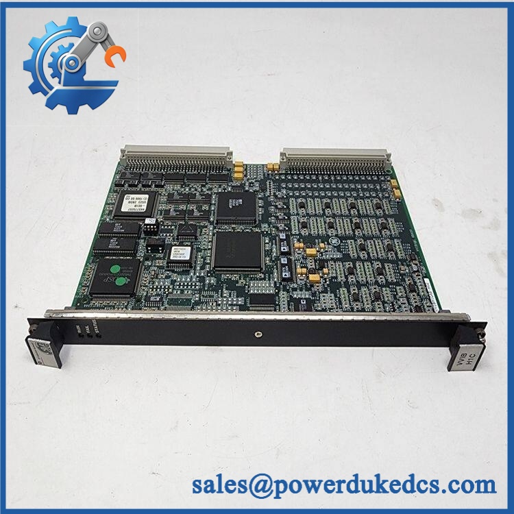
GE IS200VVIBH1C
Application Scenarios & Pain Points
At a gas-turbine plant, the VVIB can process proximity-probe information used to monitor shaft vibration and axial position. A degraded vibration channel at the board level can therefore affect machinery-protection decisions even when the turbine’s general process I/O remains healthy.
For steam-turbine machinery monitoring, Keyphasor-related information can be extracted from applicable proximity measurements, supporting shaft-speed and phase analysis. Incorrect terminal-board pairing or sensor excitation problems can mimic a failed VVIB (verify the field circuit before replacing the VME board).
In large rotating compressors, vibration signals can contain both low-frequency position information and substantially higher-frequency dynamic content. The VVIB’s separate gap and vibration filtering paths are intended for these different measurement requirements.
At 50°C+ cabinet temperatures, aging electrolytic components, analog circuitry, and connector interfaces deserve additional inspection even when the board still passes a basic startup check.
During legacy Mark VI maintenance, the strongest pain point is traceability. The C-revision board should be matched against the installed terminal board, sensor configuration, firmware/application configuration, and VME rack position rather than substituted solely because the VVIB functional name is identical.
🚨 Common Error Codes & Diagnostic Symptoms
Symptom/Code: FAIL LED illuminated → Diagnosis: The board may have detected an internal processing, power, conversion, or diagnostic fault; field-sensor problems should be ruled out first. → Action: Review Mark VI diagnostics, verify terminal-board excitation and field wiring, then replace the VVIB if the failure follows the board.
Symptom/Code: Multiple vibration channels become invalid simultaneously → Diagnosis: A common excitation, terminal-board, backplane, or VVIB hardware problem is more likely than simultaneous failure of multiple probes. → Action: Check the -28 VDC probe supply, terminal-board connections, P1/P2 seating, and controller diagnostics before replacing individual sensors.
Symptom/Code: Position signal appears incorrect while vibration channels remain active → Diagnosis: Gap-filter configuration, probe excitation, sensor gap, or the position-processing path may be involved. → Action: Verify probe bias/gap and terminal-board wiring, then test the VVIB channel with an approved signal simulator.
Exact diagnostic identifiers depend on the Mark VI software release and configured machinery-monitoring application. Use the controller event record and board LEDs as the primary diagnostic evidence.
🚨 Cross-Reference & Lifecycle Migration
The IS200VVIBH1C is a legacy Mark VI vibration-monitoring board. It should not be confused with later Mark VIe vibration modules such as IS220PVIBH1A or safety-oriented IS220YVIBS1A; those belong to different distributed-I/O architectures and are not automatic replacements. GE’s later certification documentation identifies the PVIB and YVIBS families with their own terminal-board combinations.
For the older Mark VI architecture, the VVIB works with TVIB/DVIB terminal boards and VME backplane connections. Up to 14 probes can be connected through the terminal-board arrangement, and the associated field interface determines the actual sensor configuration.
Lifecycle status: Legacy / Limited. Plan inventory accordingly. Plants still dependent on Mark VI should maintain a verified spare because an aging vibration card can be difficult to replace during an outage, while migration to Mark VIe generally requires a broader engineering conversion rather than a board-for-board substitution.
Firmware flashing is not something to treat casually. The VVIB contains active processing logic, FPGA resources, and memory, but firmware/configuration compatibility is governed by the complete Mark VI control application; preserve the existing software baseline before attempting any replacement or reconfiguration.
Field Engineer’s Tech Notes
First warning: do not condemn the VVIB before measuring probe excitation. The board supplies the Proximitor circuitry, and a failed regulator, shorted field circuit, or damaged terminal connection can make several channels appear defective at once.
Second warning: protect the P1/P2 backplane connectors. Slide the board into the VME rack using the correct guide position, fully seat both edge connectors, then secure the captive front-panel hardware. Do not force a board into a slot with misaligned guides; damage to the backplane connector can turn a straightforward card replacement into a cabinet-level repair.
Keep the conformal-coated PCB in ESD-controlled handling conditions. Coating protects against environmental contamination; it does not make the exposed connector contacts immune to electrostatic discharge or mechanical damage.
Strict QA & Testing SOP
Step 1 — Inbound inspection. Verify IS200VVIBH1C, C revision, serial/date markings where available, faceplate condition, coating condition, P1/P2 connectors, and RUN/FAIL/STATUS indicators. Photograph the complete board.
Step 2 — Mechanical examination. Inspect the VME edge connectors under magnification. Check the faceplate retaining screws, guides, connector housings, and PCB for contamination, lifted components, cracked solder joints, or heat discoloration.
Step 3 — Power-path verification. On an approved test fixture, verify the required board supply rails and the Proximitor excitation path. Confirm that the protected negative excitation sources behave normally before applying simulated sensor signals.
Step 4 — VME communication test. Install the board in a controlled Mark VI VME chassis. Confirm board recognition, RUN/FAIL/STATUS behavior, backplane communication, and diagnostic reporting.
Step 5 — Sensor simulation. Apply controlled simulated proximity, vibration, or position signals through the appropriate TVIB/DVIB interface. Verify channel acquisition and expected measurement response.
Step 6 — Dynamic signal testing. Exercise applicable vibration-processing channels across representative frequencies, including the documented wideband filtering regions where supported. Confirm signal processing, filtering, and diagnostic behavior.
Step 7 — Channel integrity check. Verify multiple channels rather than relying on a single successful input. A common power or conversion fault can selectively affect groups of measurements.
Step 8 — Final QC. Record serial number, revision, power measurements, simulated-input results, diagnostic status, inspector, and test date. Package the PCB in ESD shielding material with rigid protection around the two rear-edge VME connectors.
Test videos are available for controlled power-up, VME recognition, and vibration-signal simulation when documented QC evidence is required.
Buyer’s FAQ
Can I hot-swap the IS200VVIBH1C?
No. The documented Mark VI installation procedure calls for the VME processor rack to be powered down before installing this board. Remove power, isolate the equipment according to the site’s procedure, and verify the correct slot before insertion.
How can I verify a New Original unit?
Check the complete GE part number, C functional revision, PCB markings, conformal coating, faceplate, P1/P2 connector condition, and serial information. For strategic turbine spares, request clear photographs and a documented bench-test report before accepting the asset.
What warranty should I specify?
Put the warranty period and condition classification directly on the purchase order, whether the unit is New Original, New Surplus, or Refurbished. Coverage should explicitly include functional failure after installation and define the return procedure.
Does the board come with the latest firmware pre-loaded?
Do not assume that it does. Firmware and configuration are tied to the installed Mark VI application and machinery-monitoring architecture; record the existing software baseline before replacement and confirm compatibility before any reprogramming activity.











 Start Chat


