

Description
- Brand: GE
- Full Model Number: IS215AEPAH1CH
- Product Type: AEPA Analog I/O Board
- System/Series Family: GE Mark VI
- Core Function: Analog I/O interface board for signal acquisition and control within a Mark VI control system
- Top 3 Hardcore Specs: Mark VI platform | AEPA board designation | Analog I/O interface
- Board Type: IS200AEPAH1A / IS215AEPAH1CH family reference
- Revision: H1 / CH hardware identification
- Stock Status: New surplus / condition to be confirmed per available unit
The GE IS215AEPAH1CH is associated with the AEPA analog I/O board family used within GE Mark VI control equipment. GE Mark VI I/O boards are installed as part of the control system’s signal interface architecture, where field measurements and control signals are exchanged with the system controller. The complete board identification should be retained during replacement because GE Mark VI boards commonly use multiple hardware and revision designations.
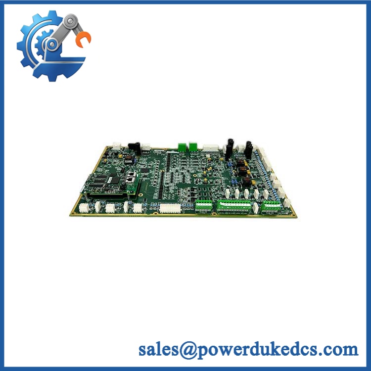
GE IS215AEPAH1CH
Module 3: Technical Product Introduction
When a Mark VI control system begins reporting abnormal analog values, the fault may originate in the field transmitter, terminal wiring, I/O interface, or controller—not necessarily in the sensor itself. GE IS215AEPAH1CH belongs to the AEPA analog I/O board family and is used as an interface between field-level analog signals and the Mark VI control architecture. For a failed board, matching the exact hardware identification is essential before restoring the cabinet to service.
The engineering advantage is signal-interface continuity: the board provides the required analog acquisition/control path without requiring the entire Mark VI system to be replaced. Exact channel count, input/output ranges, isolation characteristics, and terminal assignments should be verified against the applicable GE documentation for the specific board revision rather than inferred from the model prefix. —Do not assume that every AEPA board has identical electrical characteristics simply because the base designation is similar.
Module 4: Application Scenarios & Field Realities
- In turbine control cabinets, analog I/O boards can handle process measurements and control signals that must remain synchronized with the Mark VI control logic. A single failed channel should be investigated alongside the transmitter loop and termination wiring before replacing the board.
- During startup commissioning, verify each analog channel against a known reference rather than accepting a plausible displayed value. A scaling error can make a healthy 4–20 mA signal appear to be a sensor problem.
- For legacy Mark VI maintenance, record the board’s complete identification, connector positions, terminal wiring, and revision before removal. Mark VI installations can contain several boards with similar physical construction but different functions.
- When an analog channel intermittently drops out, inspect cabinet temperature, connector seating, field wiring, and power/reference conditions. Intermittent analog faults are often more difficult to reproduce than a completely failed channel.
Module 5: Migration, Compatibility & Installation Traps
Replacement Matrix
| Replacement Type | IS215AEPAH1CH Assessment |
|---|---|
| Drop-in Replacement | Potentially yes, when replacing the same IS215AEPAH1CH hardware configuration and compatible Mark VI installation |
| Software Compatible | Configuration-dependent; I/O channel assignments and scaling must match the existing Mark VI application |
| Hardware Modification Required | Not expected for an exact replacement; required if terminal assignments, board revision, or I/O characteristics differ |
Field Traps — Watch Out
1. Verify the complete board identification.
Do not purchase solely by the AEPA family designation. The full identification and any secondary board markings should be compared with the installed board.
2. Check the channel configuration.
Before commissioning, verify each field channel’s signal type, scaling, polarity, engineering range, and terminal assignment. An analog board can be electrically healthy while the control application is configured incorrectly.
3. Protect the board from ESD.
The PCB contains sensitive electronic circuitry. Use an ESD-controlled work area and appropriate grounding when handling or installing the replacement.
4. Inspect the mating connectors.
Loose or contaminated connectors can create intermittent analog signals. Inspect the connector contacts and cabinet wiring before concluding that a newly installed board is defective.
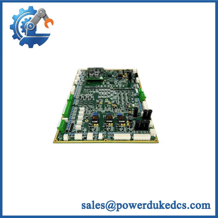
GE IS215AEPAH1CH
Module 6: Quality Assurance SOP
Before shipment, each available should pass a documented inspection sequence:
- OEM identification inspection — Verify GE markings, complete designation, board labels, revision information, and associated AEPA markings.
- OEM anti-counterfeit visual inspection — Examine PCB construction, component markings, connectors, labels, solder joints, and evidence of unauthorized rework.
- Physical inspection — Check the PCB, connector interfaces, mounting points, terminal areas, and board surfaces for cracks, corrosion, contamination, or mechanical damage.
- Part-number verification — Confirm the physical board against the customer’s exact requirement before testing.
- Power-on self-test (POST) — Where the compatible Mark VI test environment supports it, power the board and check system diagnostics for initialization or board-level faults.
- Analog channel simulation — Apply controlled reference signals appropriate to the verified board specification and confirm correct channel response.
- Input/output verification — Test applicable analog channels individually and compare measured values against the known reference.
- Communication/interface verification — Install the board in a compatible Mark VI test environment and verify that the control system recognizes the I/O hardware and receives valid channel data.
- Alarm/diagnostic verification — Confirm that simulated abnormal signal conditions produce the expected diagnostic response where supported by the test configuration.
- Extended stability test — Operate the board under controlled conditions and monitor for intermittent channel loss, abnormal temperature, resets, or communication faults.
- Final visual inspection — Recheck connectors, labels, PCB condition, and mounting features after testing.
- Test record and packaging — Record the part number, revision, channel-test results, inspection date, and packaging condition before dispatch.
QA note: Because this is an analog I/O board, a power-on check alone is not sufficient. Controlled signal simulation across the applicable channels provides substantially stronger evidence that the board is operational than simply confirming that the Mark VI rack recognizes it.











 Start Chat


