

Description
- Brand: GE
- Full Model Number: IS215UCCCM04AB
- System/Series Family: Mark VIe / UCCC Universal Controller C
- One-Sentence Core Function: 6U CompactPCI controller executing Mark VIe turbine-control applications and coordinating UDH, CDH, and IONet communications
- Top 3 Hardcore Specs: Intel Pentium M 1.6 GHz; 256 MB DDR SDRAM; 128 MB CompactFlash
- Controller Architecture: Single-slot 6U CPCI
- Operating System: QNX Neutrino
- UDH/CDH Interfaces: 10/100/1000Base-TX
- IONet Interfaces: R, S, T private Ethernet networks through integrated EPMC
- Serial Interface: RS-232 service/configuration port
- Control Architectures: Simplex, dual, TMR
- Status Monitoring: Power, run, watchdog, link/activity, temperature indication
- Stock Status: New Surplus / Fully Tested Refurbished subject to availability
Module 3: Commercial-Technical Deep Dive
A failed IS215UCCCM04AB can take an entire Mark VIe control path offline because this is the controller executing the application, not a peripheral communication card. The UCCC platform was built for turbine and balance-of-plant control, using a 1.6 GHz Intel Pentium M processor, 256 MB DDR SDRAM, 128 MB CompactFlash, and a 6U CompactPCI form factor. Two Gigabit Ethernet interfaces provide the UDH/CDH connection path, while the integrated EPMC mezzanine supplies the dedicated R, S, and T IONet interfaces used to communicate with Mark VIe I/O packs. GE-compatible documentation also identifies QNX Neutrino as the operating environment.
The practical advantage is architectural isolation: control traffic and I/O traffic can remain on their intended Ethernet paths rather than being collapsed into one generic network interface. The controller also supports simplex, dual-redundant, and TMR system arrangements, making the exact board configuration important during replacement. The published temperature range is 0 to +50°C operating and -40 to +85°C storage, with 5% to 95% non-condensing humidity. These values matter in turbine cabinets where cabinet temperature, airflow, and fan condition can materially affect processor stability. Technically, the 1.6 GHz clock rate alone does not determine compatibility; the installed QNX image, UCCC revision, EPMC configuration, application image, and Mark VIe project configuration are equally important.
Module 4: Compatibility & Installation Traps
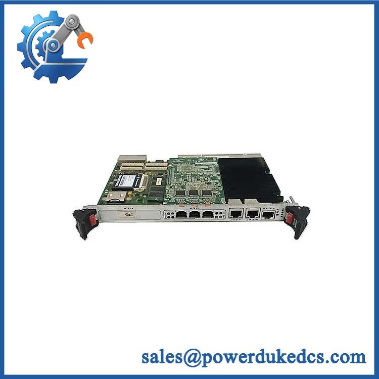
GE IS215UCCCM04AB
Migration/Compatibility
- System role: Mark VIe UCCC controller / CPCI processor assembly.
- Mechanical platform: 6U CompactPCI, single-slot installation.
- Controller configuration: The published M04 assembly uses a 1.6 GHz Pentium M processor, 256 MB DDR SDRAM, 128 MB CompactFlash, and an integrated EPMC mezzanine.
- Operating environment: QNX Neutrino; preserve the existing application image and controller configuration rather than assuming a blank replacement board is immediately application-ready.
- Network architecture: Verify UDH, optional CDH, and IONet R/S/T assignments before commissioning.
- Redundancy: For dual or TMR installations, verify the replacement controller’s role and synchronization configuration before returning the system to service.
- Logic rewrite: Normally not required merely because the same controller assembly is replaced, but application restoration, configuration download, firmware/image matching, and redundancy validation may be required.
- Revision matching: Treat IS215UCCCM04AB as the exact procurement target. The suffix should be matched against the installed unit rather than assuming every UCCC board has identical hardware.
⚠️ Field Traps (Watch Out)
1. Do not treat this as a generic hot-swappable PC board.
The controller contains the application processor, non-volatile storage, and network interfaces that form part of the Mark VIe control architecture. A redundant system may support online replacement procedures, but the maintenance method must match the actual simplex, dual, or TMR configuration. Documentation for this exact assembly states that the CPCI rack should normally be de-energized before installation or removal unless an approved online replacement is being performed on a redundant system.
2. Verify the battery and stored configuration before commissioning.
Available installation guidance states that the CMOS battery may be disconnected during storage and that the battery jumper must be restored before installation. A replacement controller can therefore require a configuration/time check even when the board itself passes its electrical test.
3. Do not confuse UDH/CDH with IONet.
The controller uses separate network paths for higher-level controller communication and the private R/S/T IONets. Incorrect patching can make a healthy CPU look like an I/O network failure.
Module 5: Quality Assurance SOP
Each available IS215UCCCM04AB should undergo a documented board-level inspection and functional test before shipment:
- OEM anti-counterfeit visual inspection: Verify GE identification, complete catalog number, revision markings, PCB construction, front-panel layout, connector arrangement, component population, and EPMC installation.
- Assembly verification: Record the complete IS215UCCCM04AB designation and any readable board or assembly identifiers.
- PCB condition inspection: Check for corrosion, contamination, cracked components, damaged connectors, bent pins, lifted components, heat damage, and evidence of prior repair.
- ESD inspection and handling: Use a grounded ESD workstation and inspect static-sensitive areas before power application.
- Power-on self-test (POST): Install the controller in an approved Mark VIe/CPCI test fixture and verify power, processor initialization, memory recognition, CompactFlash detection, and expected status indication.
- LED diagnostic check: Verify power, run/status, watchdog, Ethernet activity, and temperature-related indications under controlled test conditions.
- Communication handshake verification: Test the UDH path and, where the fixture supports it, the CDH interface and IONet R/S/T communication paths.
- Processor and memory verification: Confirm the expected 1.6 GHz Pentium M and 256 MB memory configuration where accessible through the service environment.
- Storage verification: Confirm 128 MB CompactFlash recognition and controlled boot behavior using an approved test image.
- Redundancy validation: For units designated for dual or TMR applications, perform the applicable controller synchronization and failover test without altering the customer’s production configuration.
- Watchdog verification: Confirm watchdog monitoring and expected recovery behavior through the approved diagnostic procedure.
- Temperature monitoring check: Verify controller temperature reporting and warning behavior under controlled conditions.
- Final QC record: Record catalog number, revision, serial/trace information where available, test image, communication results, LED results, and technician sign-off.
- ESD-safe packaging: Seal the tested controller in ESD-safe packaging with mechanical protection around the CPCI connectors and front panel.
The available technical data identifies this assembly with diagnostic functions covering watchdog status, temperature monitoring, EPMC power monitoring, and IONet packet monitoring. Those functions should be included in the bench-test record when the corresponding test equipment is available.
Module 6: CRO-Driven Buyer FAQ
Is the GE IS215UCCCM04AB obsolete?
The is a legacy GE Mark VIe controller assembly rather than a current-generation controller. It remains relevant for installed Mark VIe turbine and plant-control systems where the existing CPCI architecture and software environment must be maintained. Current procurement should verify the exact suffix, installed configuration, and test condition rather than relying on a generic UCCC description.
Is the a PLC CPU or a communication module?
It is a CPCI controller board that acts as a primary control processor within the Mark VIe architecture. It executes the control application and manages communications through UDH/CDH and the dedicated IONet interfaces. Calling it a simple communication card understates its role in the control system.
Can the be replaced while the system is powered?
Do not assume live insertion is permitted in every installation. Available installation guidance specifies de-energizing the CPCI rack before removal or installation unless the work is being performed under the approved online-replacement procedure for a redundant system. A simplex controller replacement should be handled as a planned control-system maintenance event.
What should I verify before ordering this exact controller?
Provide the complete part number and, where available, the existing system serial number and material-list information. Confirm the installed processor configuration, CompactFlash arrangement, EPMC mezzanine, UDH/CDH architecture, IONet assignments, and simplex/dual/TMR role. A visually similar UCCC board is not automatically an interchangeable replacement.
What warranty and technical support should I expect?
Warranty duration should be specified against the actual unit condition and test status on the quotation. Technical support should cover part-number identification, revision matching, configuration review, installation guidance, communication testing, and test documentation. Application-specific Mark VIe engineering, safety-controller code handling, or production-system commissioning should not be represented as included unless expressly stated.











 Start Chat


