

Description
- Brand: GE Energy
- Full Model Number: IS215WEPAH2B
- Additional Part Number: 109W3914P003
- Product Type: Wind Energy Pitch Axis Control PCB
- System/Series Family: Mark VIe Speedtronic
- Core Function: Controls and monitors wind turbine blade pitch-axis signals and actuator interfaces
- Top 3 Hardcore Specs: 8 analog inputs | 20 discrete inputs | 2 RS-485 interfaces
- Additional I/O: 1 incremental encoder input | 2 PWM outputs | 9 relay outputs
- Power: 125 VDC nominal
- Stock Status: New surplus / condition to be confirmed per available unit
The GE IS215WEPAH2B, associated with 109W3914P003, is a Mark VIe WEPA Wind Energy Pitch Axis control board. Published technical references identify the board with 8 analog inputs, an incremental encoder input, 20 discrete inputs, 2 discrete outputs, 9 relay outputs, 2 RS-485 interfaces, and 2 PWM control outputs.
Module 3: Technical Product Introduction
Blade pitch control is a closed-loop job: the controller has to read position and status feedback, process operating commands, and deliver the appropriate actuator signals. GE IS215WEPAH2B is a dedicated Mark VIe wind-energy pitch-axis PCB for that control layer. The board is associated with GE wind-turbine control architecture and incorporates the AEPAH1B and BPPC daughterboards.
Its I/O density is the practical advantage. The published configuration includes 8 analog inputs, 20 discrete inputs, 1 incremental encoder input, 2 discrete outputs, 9 relay outputs, 2 RS-485 interfaces, and 2 PWM outputs. References also identify a 125 VDC power-supply rating and support for 10, 20, and 40 ms software frame rates. The 109W3914P003 identifier is also documented in connection with the IS215WEPAH2B board assembly.
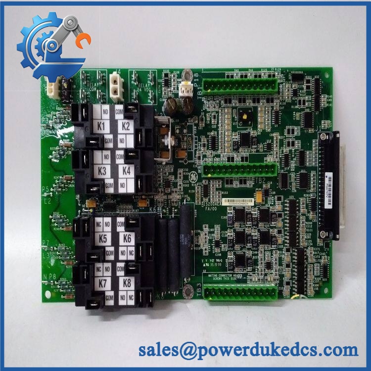
GE IS215WEPAH2B 109W3914P003
Module 4: Application Scenarios & Field Realities
- Inside a wind-turbine nacelle control cabinet, the WEPA board handles a large collection of pitch-axis signals. The encoder input is particularly important because the controller needs reliable blade-position feedback before closed-loop pitch control can be trusted.
- When a turbine reports pitch-position or actuator faults, check the complete signal chain. Encoder wiring, discrete limit/status inputs, PWM actuator connections, and RS-485 devices should be inspected before replacing the PCB.
- For turbines using redundant control architecture, verify the installed system configuration before substitution. Published references identify the IS215WEPAH2B as suitable for simplex or triple-redundant applications.
- During a planned board replacement, document every connector and daughterboard interface before removal. This is especially important because the WEPA assembly incorporates attached boards rather than functioning as an isolated bare PCB.
Module 5: Migration, Compatibility & Installation Traps
Replacement Matrix
| Replacement Type | IS215WEPAH2B / 109W3914P003 Assessment |
|---|---|
| Drop-in Replacement | Yes, when replacing the same IS215WEPAH2B / 109W3914P003 configuration in a compatible Mark VIe wind-turbine system |
| Software Compatible | Configuration-dependent; pitch-axis parameters, I/O assignments, and application software must be verified |
| Hardware Modification Required | Not expected for an exact replacement; required if board revision, daughterboard configuration, or connected I/O differs |
Field Traps — Watch Out
1. Match both identifiers.
The board should be verified as IS215WEPAH2B and, where applicable, 109W3914P003. Do not substitute another WEPA revision simply because its front-panel appearance is similar.
2. Verify the power arrangement.
Published references identify a 125 VDC nominal power rating for this board. Confirm the actual cabinet supply and wiring before energization.
3. Preserve encoder wiring and polarity.
An incorrect incremental-encoder connection can produce erroneous pitch-position feedback. Record connector pinning and signal routing before removing the existing board.
4. Check the daughterboards.
The IS215WEPAH2B incorporates the AEPAH1B and BPPC boards. Inspect their connections and physical condition during replacement rather than treating the WEPA assembly as a single independent PCB.
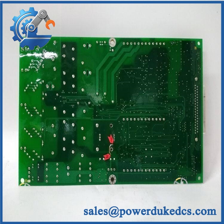
GE IS215WEPAH2B 109W3914P003
Module 6: Quality Assurance SOP
Before shipment, each available GE IS215WEPAH2B / 109W3914P003 should pass a documented inspection sequence:
- OEM identification inspection — Verify GE markings, IS215WEPAH2B designation, 109W3914P003 identification, revision markings, serial information, and daughterboard labels.
- OEM anti-counterfeit visual inspection — Examine PCB construction, component markings, conformal coating, connectors, labels, solder workmanship, and evidence of unauthorized modification.
- Physical inspection — Check the PCB, daughterboards, connectors, mounting points, terminal interfaces, and coating for cracking, corrosion, contamination, or mechanical damage.
- Part-number verification — Confirm both the IS215WEPAH2B model and applicable 109W3914P003 assembly identifier before testing.
- Controlled power-on test — Apply the specified DC supply using a protected laboratory test setup and verify normal initialization without abnormal current draw.
- Analog-input simulation — Apply controlled reference signals to applicable analog channels and verify expected acquisition and scaling behavior.
- Discrete-I/O verification — Exercise representative discrete inputs and outputs using an approved low-voltage test fixture.
- Encoder-interface verification — Apply a suitable simulated incremental-encoder signal and verify correct detection of representative position/pulse activity.
- PWM output verification — Check applicable PWM outputs using suitable measurement equipment and confirm expected signal generation.
- RS-485 communication handshake verification — Connect the applicable serial interfaces to a compatible test environment and verify communication, addressing, and data exchange.
- Relay-output verification — Test applicable relay outputs under controlled conditions and confirm correct contact-state changes.
- Extended stability test — Operate the board under controlled conditions while monitoring I/O behavior, communications, temperature, and unexpected resets.
- Final visual inspection — Recheck connectors, daughterboards, conformal coating, labels, and mounting features after testing.
- Test record and packaging — Record the model, assembly number, revision, test results, inspection date, and packaging condition before dispatch.
QA note: This board should not be validated merely by confirming that it powers up. Its value is in the pitch-axis I/O and control interfaces, so analog simulation, encoder testing, discrete I/O checks, PWM verification, RS-485 communication testing, and relay-output testing provide substantially stronger evidence of operational condition.











 Start Chat


