

Description
- Manufacturer: General Electric (GE)
- Model: IS220PDIOH1B
- GE Material / Ordering Number: 336A5026ADP6
- Product Type: Mark VIe Discrete Input/Output I/O Pack
- Core Function: Combined discrete-input and relay-output interface between one or two I/O Ethernet networks and a compatible terminal board.
- Input Capacity: 24 discrete contact inputs
- Output Capacity: 12 Form C relay outputs
- Network Interfaces: 2 RJ-45 Ethernet ports
- Terminal Interface: DC-62 connector directly mating with the associated terminal board.
- Power Interface: 3-pin, 28 VDC input
- Approximate Dimensions: A controlled mechanical dimension was not established in the reviewed GE documentation; use the cabinet drawing or physical unit for final enclosure planning.
- Estimated Shipping Weight: Use the actual packed unit for freight documentation; public supplier figures vary and should not be treated as a controlled GE specification.
- What’s in the Box: IS220PDIOH1B I/O pack unless the purchase order explicitly includes the compatible terminal board, option board, cables, or documentation.
Product Introduction
In a Mark VIe installation, the IS220PDIOH1B sits between the Ethernet control network and the field discrete interface. GE specifies the PDIO as a combined functional equivalent of the PDIA discrete-input pack and PDOA discrete-output pack, allowing one assembly to process up to 24 contact inputs and control up to 12 relay outputs.
The H1B version is particularly important for lifecycle replacement because GE identifies its processor implementation as a functionally compatible BPPC board, supported in the ControlST software suite V04.04 and later. System topology also changes the hardware requirement: one PDIO is used for simplex operation, while three PDIO packs are used for TMR signal paths.
Core Technical Specifications
| Parameter | Value |
|---|---|
| Manufacturer | General Electric |
| Model | IS220PDIOH1B |
| Material / Ordering Number | 336A5026ADP6 |
| Platform | Mark VIe / Mark VIeS |
| Product Type | Discrete Input/Output I/O Pack |
| Digital Inputs | 24 DI |
| Relay Outputs | 12 Form C contact outputs |
| Input Isolation | Optical isolation to 1500 V, group isolation |
| Input Filter | 4 ms hardware filter |
| Relay / Coil Monitoring | 12 relay/coil monitors |
| Fuse Feedback | 3 fuse-status feedbacks multiplexed to read 6 fuses |
| Ethernet | 2 RJ-45 interfaces |
| Power Input | 28 VDC |
| I/O Pack Response | Typically 4 ms from Ethernet command to output |
| SOE Monitoring | 1,000 Hz input scan for sequence-of-events monitoring |
| Diagnostics | RAM, flash, Ethernet, processor, power-supply, hardware-ID, input and relay-feedback diagnostics |
| Simplex Architecture | 1 I/O pack |
| TMR Architecture | 3 I/O packs |
| Operating Environment Rating | -40°C to +70°C for PDIOH1B enclosure design |
GE’s system guide explicitly states that the PDIOH1B is rated for -40°C to +70°C, while the older PDIOH1A is rated -30°C to +65°C. That distinction matters when qualifying a warehouse replacement by revision.
The input channels use filtering, hysteresis, and optocoupler isolation. Relay command circuits include current monitoring, while the I/O pack independently disables outputs during power-up until internal self-tests and required operating conditions have been satisfied.
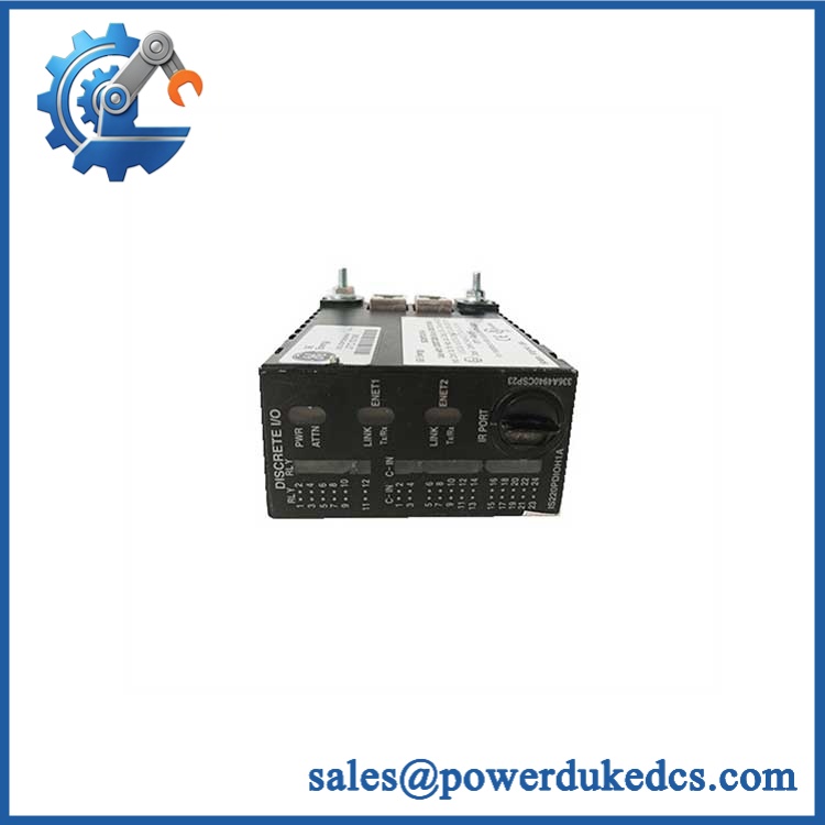
GE IS220PDIOH1B 336A5026ADP6
Global Compliance & Industry Certifications
This model has stronger hazardous-location documentation than many generic industrial I/O modules.
- ATEX: GE’s EU Declaration of Conformity lists IS220PDIOH1B as a Mark VIe Control Discrete I/O Module within the certified equipment combinations, with the applicable hazardous-location certification parameters defined in the declaration.
- IECEx / Hazardous Area: Do not infer the permitted installation category solely from the module number. The terminal-board combination and exact approved configuration remain part of the certification boundary.
- UL / cUL: Verify the certificate applicable to the complete installed Mark VIe assembly and terminal-board arrangement.
- Marine approvals: DNV and other marine approvals require separate confirmation for the intended system configuration.
- Terminal-board dependency: GE identifies specific TDBS and TDBT boards as compatible with PDIO, including versions intended for hazardous locations.
Verify specific lot certifications with OEM.
Long-Term Storage & Asset Preservation Guide
- Keep the I/O pack in ESD-protective packaging. The RJ-45 and DC-62 interfaces should remain capped or protected from contamination during storage.
- Control humidity and condensation. A clean, temperature-stable storage environment is preferred; avoid repeated thermal cycling that can produce moisture on connectors and PCB surfaces.
- Perform a pre-installation diagnostic inspection. Record the exact part number, hardware revision, serial/date information, connector condition, and visible PCB condition. GE’s own startup diagnostics check RAM, flash, Ethernet ports, processor hardware, electronic IDs, and loaded application code, so the replacement should be treated as an engineered asset rather than a generic spare.
Physical Installation Prerequisites
- Install the PDIO directly onto the correct compatible terminal board. GE documents TDBSH2A/H4A/H6A/H8A and TDBTH2A/H4A/H6A/H8A families for different voltage and redundancy configurations.
- Do not substitute terminal boards based only on mechanical fit. The terminal board determines the PDIO’s voltage capability.
- Mount the terminal board first, then plug the I/O pack directly into its connector.
- Secure the pack with the threaded studs adjacent to the Ethernet ports and adjust the mounting bracket so the DC-62 connector is not exposed to right-angle mechanical force.
- Connect ENET1 and ENET2 according to the system architecture. GE identifies ENET1 as the primary system interface and ENET2 as the redundant or secondary interface.
- Supply the specified 28 VDC input through the side power connector.
- For TMR, confirm that three PDIO packs and the appropriate TDBT arrangement are present.
- Observe GE’s wiring restrictions for hazardous-location terminal boards. For example, TDBSH8A/TDBTH8A should not be used with intrinsic-safety barriers, and certain excitation-channel wiring arrangements are specifically prohibited because they can produce diagnostics or terminal-board overheating.
- Verify relay load ratings against the actual terminal-board specification before connecting solenoids or other inductive loads. GE specifically warns that the load must not exceed the relay contact voltage/current limits.
Buyer’s FAQ
Q: What HS tariff code should be used for IS220PDIOH1B 336A5026ADP6?
A: Do not accept a supplier-generated HS code without customs review. This is a specialized industrial I/O assembly, and classification can depend on the importing country’s tariff rules and how the module is characterized as a control-system component. Obtain broker confirmation before issuing final customs documents.
Q: What is the country of origin?
A: Public commercial records commonly identify the United States, but the specific unit’s COO should be supported by documentary evidence such as a Certificate of Origin, manufacturer marking, or traceability record.
Q: Is hazardous-area certified?
A: GE’s EU conformity documentation explicitly includes in the Mark VIe/Mark VIeS hazardous-location certification documentation. The permitted installation still depends on the associated terminal board, option hardware, wiring method, and site certification boundary.
Q: Does the require configuration after replacement?
A: Yes. GE states that the pack is configured using ToolboxST, and its startup sequence checks electronic identification across the terminal board, acquisition board, and processor board before verifying that the application code loaded from flash is correct for the hardware set. A replacement should therefore be validated against the site’s approved configuration and software baseline.











 Start Chat


