

Description
- Model: IS220UCSAH1A
- Brand: GE / GE Vernova
- Series: Mark VIe
- Part Type: Mark VIe Controller / UCS Controller
- Core Function: Executes turbine-control application logic and provides the controller-side Ethernet communications interface for the Mark VIe architecture.
- Processor: Freescale PowerQUICC II Pro
- CPU Frequency: 667 MHz
- Ethernet: 5 × 100 Mbps Ethernet ports
- Nominal Input Voltage: 28 VDC
- Operating Voltage Range: 18–32 VDC
- Typical Power Consumption: 12.5 W
- Memory: 256 MB DDR
- Storage: CompactFlash, up to 2 GB
- Dimensions: Approximately 40 × 160 × 169 mm, excluding mounting bracket.
Product Introduction
A failed controller can stop an otherwise healthy Mark VIe control cabinet from executing the application, communicating with field I/O, or maintaining the required control cycle. The GE IS220UCSAH1A is the UCS-class controller used in Mark VIe architectures, built around a 667 MHz PowerQUICC II Pro processor and five 100 Mbps Ethernet ports. GE documentation identifies 28 VDC as nominal input, with an 18–32 VDC operating range and approximately 12.5 W typical consumption.
This revision is more than a CPU board in a generic sense; it is a packaged control processor intended for Mark VIe system integration. Its CompactFlash-based storage and legacy DDR memory architecture matter during spare replacement because controller revision, application image, boot media, and site configuration all need to remain aligned (especially on older turbine installations).
Core Technical Specifications
| Parameter | Specification |
|---|---|
| Manufacturer | GE / GE Vernova |
| Part Number | IS220UCSAH1A |
| Product Family | Mark VIe |
| Product Type | UCS Controller |
| Processor | Freescale PowerQUICC II Pro |
| CPU Frequency | 667 MHz |
| CPU Cores | 1 |
| Mark VIe Cores | 1 |
| L2 Cache | 64 KB |
| Operating System | QNX 6.5 |
| Ethernet Ports | 5 total |
| Ethernet Speed | 100 Mbps |
| Console Interface | RJ-45 console connection; adapter sold separately |
| USB | USB 1.1 |
| Nominal Input Voltage | 28 VDC |
| Minimum Voltage | 18 VDC |
| Maximum Voltage | 32 VDC |
| Typical Power Consumption | 12.5 W |
| Memory | 256 MB DDR |
| ECC Memory | No |
| Flash Storage | CompactFlash, up to 2 GB |
| Width | 40 mm |
| Depth | 160 mm, excluding mounting bracket |
| Height | 169 mm, excluding mounting bracket |
| Mounting Orientation | Vertical |
| Hazardous-Area Context | Certified configurations exist; installation conditions and associated hardware must be checked against the applicable certification documents. |
GE’s UCSE datasheet identifies these hardware values specifically for the IS220UCSAH1A. GE certification documentation also lists IS220UCSAH1A as a Mark VIe controller and documents approved hazardous-area configurations.
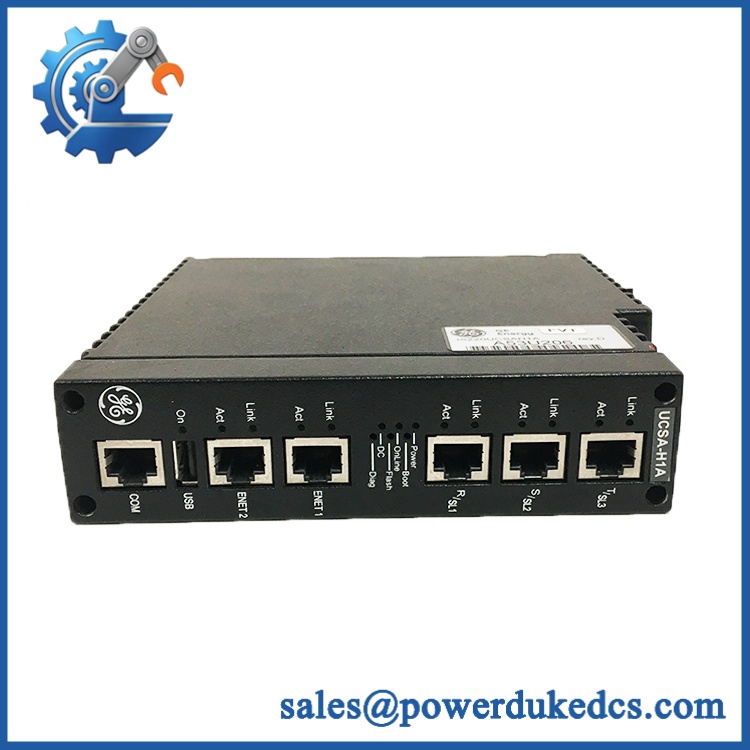
GE IS220UCSAH1A
Application Scenarios & Pain Points
Gas Turbine Control Cabinets
When the installed UCS controller stops executing its application, the issue is not limited to the processor itself; loss of controller function can interrupt the turbine control architecture. IS220UCSAH1A is associated with Mark VIe turbine control applications, making a correctly matched spare important for emergency replacement.
Power Generation MRO
A controller sitting in warehouse inventory can age differently from one operating continuously in a cabinet. For this reason, incoming inspection should verify the complete part number, revision information, storage media, connectors, and physical condition before the unit is released as a plant spare.
Legacy Mark VIe Sites
The uses a 667 MHz PowerQUICC II Pro processor, 256 MB DDR memory, and CompactFlash storage—architecture that differs materially from later UCS controller generations. Substituting a later controller solely because it carries a similar UCS designation can create software and configuration problems.
Hazardous-Location Installations
Some Mark VIe certification combinations place explicit restrictions on the controller and associated equipment. GE’s ATEX documentation, for example, identifies the in an Ex nA IIC T4 configuration with specified system conditions. Do not treat a controller’s certification status as independent of the surrounding approved assembly.
Hot, High-Duty Turbine Environments
Cabinet temperature, ventilation, and power quality remain practical failure factors even when the controller’s nominal electrical specifications are within limits. Keep the 18–32 VDC input range in view and check the actual cabinet supply during troubleshooting rather than assuming a nominal 24/28 VDC source is healthy.
Common Error Symptoms & Diagnostic Checks
Symptom: Controller does not boot or remains unavailable on the control network
→ Diagnosis: Check the 28 VDC supply at the controller terminals, verify that voltage remains above the 18 V minimum during startup, then inspect the CompactFlash media and controller status indications.
→ Action: Replace module after confirming external power and configuration are healthy.
Symptom: Controller powers up but does not communicate with the expected Mark VIe network
→ Diagnosis: Verify Ethernet port assignment, cable integrity, network configuration, and the physical UCS revision. A five-port should not be assumed interchangeable with later UCS hardware simply because both are controller products.
→ Action: Replace module after network-side checks.
Symptom: Controller repeatedly resets or becomes unstable under operating load
→ Diagnosis: Check the DC supply for transient sag, cabinet thermal conditions, and controller hardware condition. The specified typical consumption is only 12.5 W, so abnormal current demand or thermal behavior warrants investigation rather than continued operation.
→ Action: Replace module after confirming the external supply and cooling path.
Cross-Reference & Lifecycle Migration
The belongs to an earlier Mark VIe UCS controller generation. GE’s current certification references continue to list the part, while later Mark VIe controller families use different processors and substantially different computing architectures. The is specifically identified with the 667 MHz PowerQUICC II Pro processor, whereas newer UCS variants use Intel-based architectures.
For replacement planning, do not cross-reference solely by the “UCS” family name. Confirm the controller part number, application software, hardware revision, storage media, network architecture, and site-specific configuration before migration. This is particularly important when replacing an older IS220 controller with a later IS420/IS421-generation controller.
GE certification records also show formal certification activity associated with , including UL-listed Mark VIe controller documentation issued in 2026. That means the part remains relevant in documented Mark VIe configurations, but this should not be interpreted as a guarantee of unrestricted new production availability.
Spare-stock implication: For a running turbine or power-generation asset that still depends on hardware, maintaining at least one tested spare is prudent. A controller failure is a system-level event, and sourcing risk increases when a site waits until the installed unit has already failed.
Field Engineer’s Tech Notes
Tech Note 1 — Check the power source at the module, not only at the cabinet supply.
A nominal 24/28 VDC power supply does not prove that the controller is receiving clean voltage at startup. Measure directly at the controller under load and watch for transient drop. GE specifies 18 V as the minimum input for this controller.
Tech Note 2 — Never swap UCS generations by name alone.
An is based on a PowerQUICC II Pro CPU with DDR and CompactFlash architecture. Later UCS products may use Intel processors, different memory architecture, different software environments, and different system requirements. Verify the complete hardware and software baseline before installing a cross-generation substitute.
Strict QA & Testing SOP
Step 1 — Inbound Inspection
Verify manufacturer marking, complete part number, hardware revision, serial number, connector condition, mounting features, labels, and signs of storage damage or corrosion.
Step 2 — Visual PCB and Mechanical Inspection
Inspect the enclosure, ventilation openings, PCB condition, connector pins, retaining hardware, and CompactFlash interface. Check for contamination, cracked solder joints, damaged locking hardware, or evidence of rework.
Step 3 — Power-Up Test
Apply a controlled DC source within the specified 18–32 VDC operating range, using 28 VDC nominal as the reference point. Confirm normal startup behavior and record supply voltage/current.
Step 4 — Controller and Communications Test
Verify controller startup, Ethernet link negotiation, port activity, console access where applicable, and network communication using the appropriate Mark VIe test environment.
Step 5 — Storage and Configuration Verification
Inspect CompactFlash condition and verify that the installed software/application image corresponds to the intended plant configuration. Record firmware/software details rather than assuming that two visually identical controllers contain the same image.
Step 6 — Extended Run Test
Operate the unit on an appropriate test rack for an extended period. Monitor communications stability, reboot behavior, supply voltage, and temperature rise. For critical spare inventory, a controlled burn-in exceeding 24 hours is recommended.
Step 7 — Final QC and Packaging
After successful testing, record the test results, photograph labels and hardware identification, protect the controller against ESD, use anti-static packaging and shock protection, and seal the unit in a traceable carton.
QC Documentation: Test reports and test videos should be retained with the spare-part record when available, providing traceability for future MRO audits and emergency deployment.
Buyer’s FAQ
Q1. Is a controller or an I/O module?
It is a Mark VIe UCS controller, not a conventional field I/O module. GE identifies the part as a controller using a 667 MHz PowerQUICC II Pro processor.
Q2. Can be hot-swapped?
Do not assume unrestricted hot-swapping. Whether live replacement is permissible depends on the specific Mark VIe system architecture, power arrangement, cabinet procedures, and site operating instructions. Follow the applicable GE installation and maintenance procedure before removing an energized controller.
Q3. How should an OEM-original be authenticated?
Verify the physical GE marking, exact part number, revision information, serial traceability, connector condition, and hardware architecture. A genuine spare should also pass a controlled functional test rather than being accepted based only on appearance.
Q4. What warranty expectation should be used for a replacement controller?
Warranty terms depend on the supplier’s commercial offering and the unit’s condition (new, surplus, refurbished, or tested). For critical turbine-control spares, request the warranty period and the supplied test record in writing before purchase.











 Start Chat


